This article focuses on URDF modeling for a four-wheel cylindrical robot in ROS, covering the complete workflow from package initialization and geometry mapping to model validation and RViz visualization. It addresses common beginner issues in link/joint organization, dimension conversion, and display verification. Keywords: URDF, ROS, RViz.
Technical specification snapshot
| Parameter | Value |
|---|---|
| Language | XML, Bash |
| Platform | ROS1 / Catkin |
| License | CC BY-SA 4.0 (original content declaration) |
| Stars | Not provided |
| Core dependencies | urdf, xacro, robot_state_publisher, joint_state_publisher_gui, rviz, liburdfdom-tools |
| Robot structure | 1 chassis + 2 drive wheels + 2 caster wheels |
| Core files | xqrobot_base.urdf, display_xqrobot.launch |
This article provides a directly runnable four-wheel cylindrical robot modeling solution
This model targets ROS beginners and mobile robot developers who want to quickly build a chassis model that has a clear structure, accurate dimensions, and direct RViz visibility.
The robot consists of 5 links and 4 joints. The chassis is a cylinder, the left and right sides use drive wheels, and the front and rear are supported by spherical caster wheels, making it a practical starting point for differential-drive chassis modeling.
The robot parameters are mapped precisely into URDF geometry
- Chassis radius:
0.1m, height:0.08m - Drive wheel radius:
0.0325m, width:0.015m - Caster wheel radius:
0.0075m - Ground clearance:
0.015m
cd ~/ros_workspace/src/
# Create the description package and declare URDF and Xacro dependencies
catkin_create_pkg xqrobot_description urdf xacro

cd xqrobot_description/
# Create the standard directory structure for the description package
mkdir urdf meshes launch config
These commands initialize a Catkin description package and create the standard directory skeleton for a URDF project.
The directory structure of the robot description package determines long-term maintainability
You should manage models, launch files, rendering assets, and configuration files in separate directories. This structure makes it easier to extend the package later with sensors, controllers, and Gazebo simulation files.
xqrobot_description/
├── CMakeLists.txt
├── package.xml
├── urdf/
├── launch/
├── config/
└── meshes/
This directory layout is a common organization pattern for robot description packages in ROS and works well for long-term evolution.
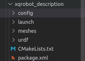 AI Visual Insight: This image shows the actual on-disk directory layout of the description package in a file manager. The key point is that the
 urdf, launch, config, and meshes directories have already been separated by responsibility, which decouples model definitions, launch logic, and visualization configuration in line with ROS engineering practices.
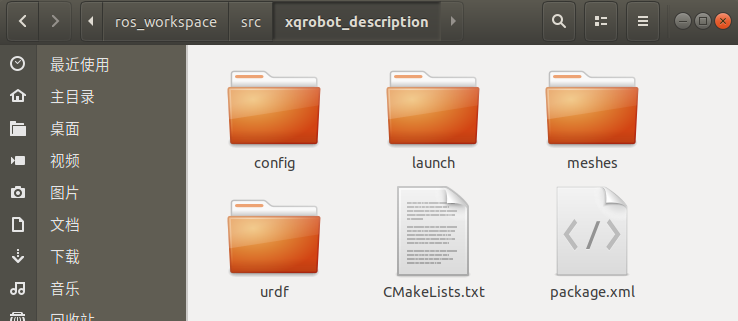 AI Visual Insight: This image further verifies the directory tree structure and helps confirm that the package name and hierarchy inside the workspace are correct, preventing model loading failures caused by bad paths in
 roslaunch or $(find pkg_name).
The core value of URDF is that it translates mechanical structure into a computable topology
In URDF, link describes rigid bodies, and joint describes connections and motion relationships. In this model, the chassis is the root node base_link, and the other four components are attached to the root through joints.
The chassis and drive wheel definitions establish the visual and motion reference frame
<?xml version="1.0"?>
<robot name="xqrobot">
  <!-- The chassis acts as the root link -->
  <link name="base_link">

<visual>
      <origin xyz="0 0 0" rpy="0 0 0"/>

<geometry>
        <!-- Cylindrical chassis: radius 0.1m, height 0.08m -->
        <cylinder radius="0.1" length="0.08"/>
      </geometry>
      <material name="yellow">
        <color rgba="1 0.4 0 1"/>
      </material>
    </visual>
  </link>

  <!-- Continuous rotation joint for the left drive wheel -->
  <joint name="left_wheel_joint" type="continuous">
    <origin xyz="0 0.08 -0.04" rpy="0 0 0"/>
    <parent link="base_link"/>
    <child link="left_wheel_link"/>
    <!-- The wheel rotates around the Y axis -->
    <axis xyz="0 1 0"/>
  </joint>
</robot>
This snippet defines the root link and one drive wheel joint, demonstrating the basic URDF pattern for geometry and topology definition.
A complete model must add the right wheel and the front and rear caster wheels
The right wheel is symmetric to the left wheel, while the front and rear caster wheels use spherical geometry. The article connects them all with continuous joints to complete visualization and hierarchical topology, rather than targeting precise physical simulation.
For introductory modeling, this approach is efficient enough. If you later integrate the model with Gazebo, you should also add collision and inertial tags; otherwise, the dynamic behavior will remain incomplete.
Validity checking is the most commonly overlooked step in URDF projects
After writing the XML, your first step should not be launching RViz. You should validate syntax and topology first. This makes it much easier to identify unclosed tags, naming conflicts, and root node errors.
sudo apt-get install liburdfdom-tools
cd ~/ros_workspace/src/xqrobot_description/urdf/
# Check URDF syntax and tree structure
check_urdf xqrobot_base.urdf
# Generate a topology graph
urdf_to_graphiz xqrobot_base.urdf
These commands validate the URDF file and generate a link-joint topology graph.
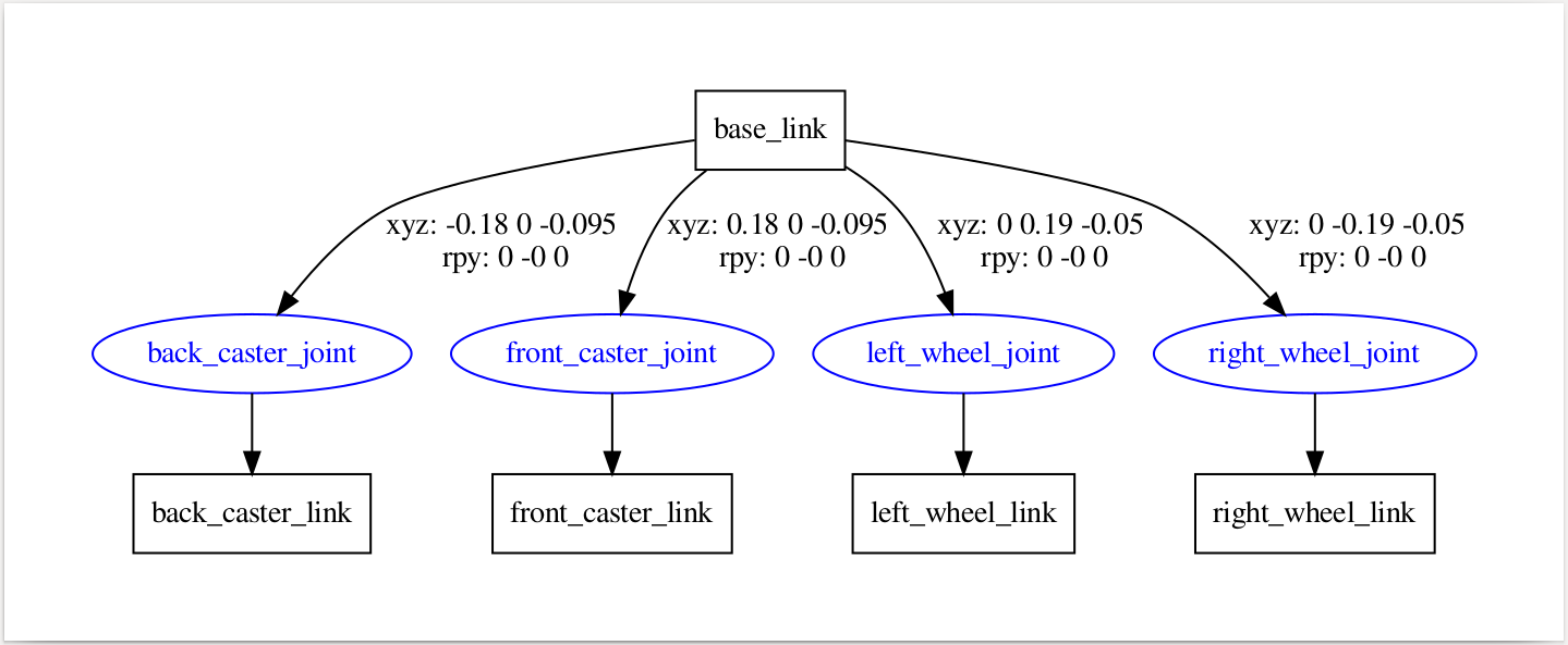 AI Visual Insight: This image shows the visualized joint tree generated from the URDF. You can clearly see
 base_link as the root node branching to the left and right drive wheels and the front and rear caster wheels, confirming that the model uses a standard single-root, multi-child topology suitable for TF publishing and RViz rendering.
The RViz launch file connects the static model to the ROS visualization pipeline
The robot_description parameter loads the URDF, joint_state_publisher_gui publishes joint states, robot_state_publisher generates the TF tree, and RViz renders the model.
<?xml version="1.0"?>
<launch>
  <!-- Load the URDF into the parameter server -->
  <param name="robot_description" textfile="$(find xqrobot_description)/urdf/xqrobot_base.urdf" />
  <!-- Enable the joint control GUI -->
  <param name="use_gui" value="true"/>
  <node name="joint_state_publisher_gui" pkg="joint_state_publisher_gui" type="joint_state_publisher_gui" />
  <!-- Publish TF relationships between links -->
  <node name="robot_state_publisher" pkg="robot_state_publisher" type="robot_state_publisher" />
  <node name="rviz" pkg="rviz" type="rviz" args="-d $(find xqrobot_description)/config/xqrobot_urdf.rviz" required="true" />
</launch>
This launch file turns model loading, joint publishing, TF publishing, and visualization into a repeatable workflow.
cd ~/ros_workspace/
catkin_make
source devel/setup.bash
# Launch the robot model display
roslaunch xqrobot_description display_xqrobot.launch
These commands compile the workspace, refresh the environment, and start RViz.
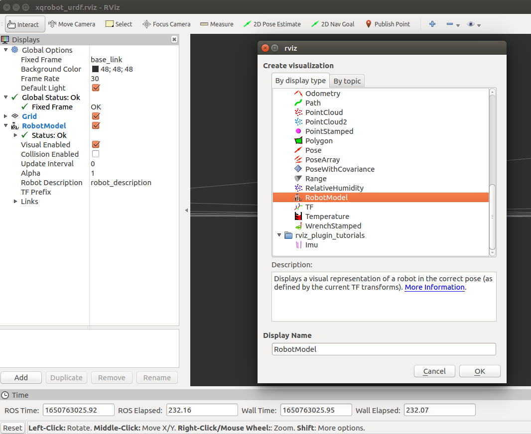
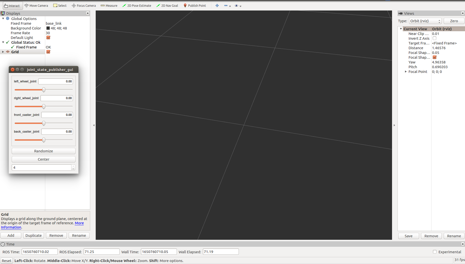 AI Visual Insight: This image shows the initial RViz interface and model loading workflow. The key step is to set
 Fixed Frame to base_link and add the RobotModel display, which is required for a URDF model to move from the parameter server into the 3D view.
 AI Visual Insight: This image reflects the state after RViz configuration is complete, indicating that the display list, coordinate frames, and model rendering parameters have already been saved into the
 .rviz configuration file, so you do not need to reconfigure them on future launches.
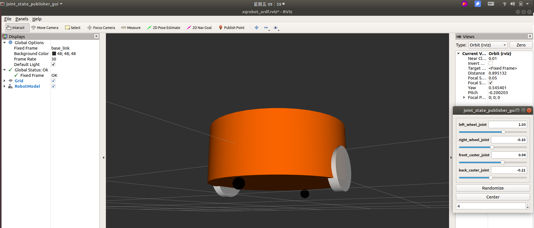 AI Visual Insight: This image directly shows the spatial arrangement of the yellow cylindrical chassis, the white drive wheels on both sides, and the black spherical caster wheels at the front and rear. It confirms that the
 origin xyz/rpy parameters generally satisfy the dimensional and ground-clearance requirements, so the model can serve as a mobile robot chassis prototype for further expansion.
This base model works well as a minimum viable starting point for a mobile robot system
It already covers the three most important parts of ROS modeling: geometric description, topological connection, and visualization validation. For teaching, experimentation, and prototype development, this version is sufficient to support future additions such as LiDAR, cameras, battery enclosures, and control plugins.
The next step should add dynamics and collision modeling
If your goal is simulation rather than static display, you should continue by adding the following capabilities:
collision: for collision detectioninertial: for mass and inertia calculationxacro: for parameterized reusegazebo: for physical simulation plugin integration
FAQ
1. Why can RViz display the model, but the robot still cannot be used for real simulation?
Because the current model mainly defines visual elements and lacks collision and inertial. RViz only cares about visualization, while simulation environments such as Gazebo also require collision and dynamic parameters.
2. Why do the drive wheels use continuous joints?
Because wheels must rotate continuously around a single axis, continuous is the most appropriate joint type for unrestricted angular rotation. If you are modeling a robotic arm joint with angle limits, you should use revolute instead.
3. Why should you run check_urdf before opening RViz?
check_urdf can detect XML syntax errors, incorrect parent-child link configuration, and abnormal tree structures much faster. Running static validation first can significantly reduce later debugging costs.
[AI Readability Summary]
This article systematically reconstructs the URDF modeling workflow for a four-wheel cylindrical robot chassis. It covers requirement breakdown, creation of the xqrobot_description package, URDF structure authoring, validity validation, and RViz visualization. The content emphasizes link/joint modeling logic, key dimension mapping, and practical ROS implementation steps, making it well suited for quickly building a foundational mobile robot model.