The Baumer VCX series covers both GigE Vision and USB3 Vision. The biggest difference between them is the power path, while trigger capability is unified through the 8-pin Hirose interface. This article focuses on three high-frequency integration issues: stable power delivery, trigger wiring, and SDK configuration. Keywords: Baumer VCX, GigE Vision, hardware trigger.
Technical Specifications at a Glance
| Parameter | Details |
|---|---|
| Vendor / Series | Baumer VCX |
| Interface Type | GigE Vision (VCXG), USB3 Vision (VCXU) |
| Primary Protocols | IEEE 802.3af/at, USB 3.0, GenICam, BGAPI |
| Typical Power Options | PoE, USB bus power, external 12–24V DC via 8-pin |
| Trigger Interface | 8-pin Hirose HR10A |
| Development Language | C++ |
| Core Dependencies | BGAPI SDK, Camera Explorer |
| GitHub Stars | Not provided in the source |
The key takeaway is that the power strategy determines system stability
The Baumer VCX series splits into two product paths: VCXG and VCXU. The former uses Ethernet and fits long-distance runs, multi-camera systems, and centralized cabling. The latter uses USB3 and fits short-distance direct connections and desktop-style deployments.
What actually determines project success is not the interface name itself. It is whether power delivery is sufficient, whether I/O is wired correctly, and whether the trigger mode matches the physical signal path.
 AI Visual Insight: This image shows the VCX series industrial camera form factor and structural layout. You can typically identify the lens mount surface, the primary data interface, and the side I/O area. This physical design indicates a machine vision deployment focus, emphasizing a compact body, standardized interfaces, and industrial mounting methods.
GigE and USB3.0 differ first in their power source
The primary power path for VCXG is PoE or external power through the 8-pin connector. The primary power path for VCXU is USB bus power or external power through the 8-pin connector. Both can use the 8-pin port for power and I/O, but the default risk profile is very different.
In industrial environments, treat “the camera powers on” and “the camera acquires stably” as two different states. The former only proves that the device is energized. The latter confirms that the acquisition path, power margin, and trigger timing are all valid.
The GigE version is better suited for long-distance and multi-device synchronized deployments
VCXG uses an RJ45 Gigabit Ethernet link. Its typical advantages are long cable distance, flexible network topology, and the ability to carry both data and power over PoE.
If camera power consumption is close to the upper limit, verify that the PoE switch supports 802.3at. Devices that support only 802.3af may cause disconnects, enumeration failures, or dropped frames on higher-load models.
 AI Visual Insight: This image compares GigE and USB3 models in terms of data interface, power method, and application scenarios. The main points usually include RJ45 with PoE capability, USB3 bus power limitations, and the shared 8-pin Hirose connector as the common entry point for external power and I/O.
// VCXG power selection example
bool UseExternalPower(bool poe_supported, bool power_enough) {
    if (!poe_supported) return true;   // The switch does not support PoE, so external power is required
    if (!power_enough) return true;    // PoE power is insufficient, switch to external 8-pin power
    return false;                      // Otherwise, prefer PoE to simplify cabling
}
This code expresses the VCXG power selection logic: PoE is reliable only when the protocol is supported and the available power is sufficient.
Key implementation points for VCXG power delivery
- Do not use PoE and external 8-pin power at the same time. The original source explicitly states that once external power is connected through the 8-pin port, PoE is disabled.
- If the system disconnects frequently in the field, check power first, then verify the IP subnet and Ethernet cable quality.
- In multi-camera deployments, also verify switch backplane bandwidth and Jumbo Frame configuration.
The USB3 version depends more heavily on external power for full-load operation
Although VCXU supports USB bus power, the theoretical USB 3.0 power ceiling is only about 4.5W. For high-resolution, high-frame-rate, or actively cooled models, this usually does not leave enough margin.
As a result, the most common mistake with the USB3 version is not “the data cable is missing,” but “only the data cable is connected.” After you add external 12–24V power, you must still keep the USB cable connected because it carries data rather than serving as a replacement for power.
 AI Visual Insight: This image emphasizes the separation between the power path and the data path in industrial cameras, especially for USB3 models where the USB data connection must remain in place even when external power is used. This distinction is critical during field troubleshooting because “powered on” does not mean “image transport is established.”
Follow an external power first principle for USB3 deployments
If the project targets long-term operation, continuous image acquisition, or high-temperature environments, use external power through the 8-pin connector by default. Direct USB power is better suited for low-power devices, lab setups, and short validation runs.
// VCXU connection check example
bool CameraReady(bool usb_connected, bool ext_power_ok) {
    return usb_connected && ext_power_ok; // USB carries data, external power provides stability
}
This code emphasizes the dual requirement for VCXU: you need both the data path and the power path.
The 8-pin Hirose interface is the unified entry point for power and triggering
Both VCXG and VCXU use the 8-pin Hirose HR10A connector for external power and I/O. Common definitions include V+, GND, and Line0 through Line3. Line0 is often configured as the trigger input, while Line1 is often configured as the strobe output.
That means the trigger configuration approach does not change across interface variants. What you actually need to verify is the pin definition for the exact model, its electrical specifications, and input level compatibility.
| Pin | Signal | Function |
|---|---|---|
| 1 | V+ | Power input |
| 2 | V+ | Parallel power input |
| 3 | GND | Power ground |
| 4 | GND | I/O reference ground |
| 5 | Line0 | Commonly used as Trigger In |
| 6 | Line1 | Commonly used as Strobe Out |
| 7 | Line2 | Configurable I/O |
| 8 | Line3 | Configurable I/O |
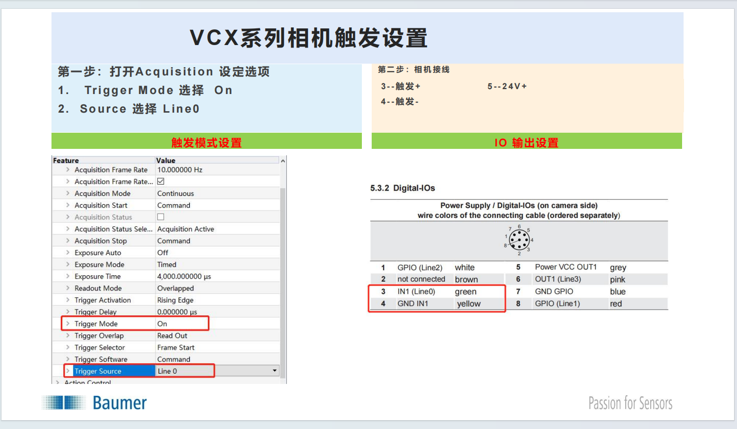 AI Visual Insight: This image shows the trigger parameter page in the official configuration tool, typically including GenICam nodes such as TriggerMode, TriggerSource, and TriggerActivation. It highlights that software configuration must match the hardware wiring exactly. Otherwise, even if the trigger signal reaches the camera, acquisition may still fail because the wrong source is selected.
The BGAPI hardware trigger workflow remains the same across both interfaces
Whether the camera is VCXG or VCXU, once you enter the remote device node map, the trigger-related configuration flow is the same. This is exactly the value of the GenICam abstraction layer.
#include "bgapi2_genicam/bgapi2_genicam.hpp"
#include
<iostream>

void ConfigureHardwareTrigger(BGAPI2::Device* device) {
    // Get the remote device node map
    BGAPI2::NodeMap* node_map = device->GetRemoteNodeList();

    // Enable trigger mode
    node_map->GetNode("TriggerMode")->SetString("On");

    // Select Line0 as the hardware trigger source
    node_map->GetNode("TriggerSource")->SetString("Line0");

    // Set rising edge triggering
    node_map->GetNode("TriggerActivation")->SetString("RisingEdge");

    std::cout << "Hardware trigger configuration completed" << std::endl;
}
This code completes the standard BGAPI hardware trigger initialization flow: enable triggering, assign the input line, and define the trigger edge.
Verify free-run mode first when debugging trigger issues
If the trigger does not respond, first set TriggerMode to Off. Confirm that free-run acquisition works normally, then return to the hardware trigger path and continue troubleshooting.
Next, use a multimeter or oscilloscope to confirm that the trigger signal actually reaches the target pin. This prevents you from misclassifying a hardware issue as a software issue.
Common failures usually come down to insufficient link budget or incorrect mapping
If the camera cannot be detected, focus on the IP subnet, PoE, and cable quality for VCXG. For VCXU, focus on the USB controller, cable quality, and external power.
If frames drop frequently, check Jumbo Frames, switch bandwidth, and PoE power for GigE. For USB3, check host controller compatibility, whether the camera is routed through a hub, and whether power remains stable.
 AI Visual Insight: This image supports the field debugging theme and typically represents the full system interaction across power, communication, and triggering in an industrial vision setup. It reminds developers to troubleshoot the camera, power supply, NIC or USB controller, and PLC trigger source as one integrated system.
This practical troubleshooting checklist is reusable in the field
// Minimal troubleshooting sequence
void DebugChecklist() {
    // 1. First confirm that the camera has stable power
    // 2. Then confirm that the data link is established
    // 3. Finally confirm that TriggerMode and the line mapping match
}
This pseudocode summarizes the field troubleshooting order: power first, then link, then trigger.
FAQ
Q: Can a Baumer VCXU run reliably for long periods with only a USB cable connected?
A: Usually no. USB3 bus power has a limited upper ceiling, and high-resolution or high-frame-rate models can easily become unstable when power is insufficient. In industrial environments, prioritize external 12–24V power through the 8-pin connector.
Q: Why does a Baumer VCXG still disconnect or drop frames when using PoE?
A: Common causes include insufficient PoE power, a switch that supports only 802.3af, Jumbo Frames not enabled on the NIC, or bandwidth saturation in multi-camera deployments. Verify the power budget first, then check the network configuration.
Q: The hardware trigger line is already connected, but the camera still does not respond. What should I do?
A: First switch to free-run mode and verify that the camera itself can acquire images normally. Then check the 8-pin pinout, verify that TriggerSource matches Line0, and confirm that the trigger edge and input level are compatible.
Core Summary: This article systematically explains the power differences between GigE and USB3.0 variants of the Baumer VCX series industrial cameras, along with 8-pin Hirose pin definitions, hardware trigger configuration, and common troubleshooting practices, helping machine vision developers complete a stable integration quickly.