For ASIC/FPGA digital front-end system design, this article distills a methodology with high factual density: first define the software-hardware interface, then partition and decouple modules, next identify performance bottlenecks using Roofline and PCIe/DDR/NoC metrics, and finally complete FPGA/ASIC cost estimation. Keywords: digital front-end, system design, performance evaluation.
Technical Specification Snapshot
| Parameter | Details |
|---|---|
| Domain | Digital front-end system design, ASIC, FPGA |
| Core Languages | Verilog / SystemVerilog / Python |
| Key Protocols | PCIe, AXI/AXIS, DDR/HBM, DMA |
| Article Type | Methodology refactoring and architecture practice summary |
| GitHub Stars | Not provided in the source material |
| Core Dependencies | DMA engine, queue management, scheduler, on-chip memory, NoC/memory controller |
System design must converge external interfaces first
System architecture design does not start with writing RTL. It starts by freezing the input and output boundaries. For digital front-end engineers, interface definitions determine subsequent module responsibilities, validation scope, and the collaboration model with software.
Top-level physical interfaces are usually constrained by the overall hardware architecture, such as the PCIe generation, lane count, data width, and clocking scheme. What is often underestimated is the software-hardware interaction interface: the DMA descriptor format, queue model, result write-back path, and how the CPU efficiently submits tasks.
The key to a software-hardware interface is not merely connectivity, but efficient collaboration
Take a data center accelerator card as an example. The link capability of PCIe Gen3 x8, Gen4 x8, or even Gen5 is usually clear. The real challenge is not the PHY. It is software submission efficiency, address alignment, outstanding depth, and return format.
# Simplified model for estimating effective PCIe bandwidth
pcie_effective_bw = (
    link_bw              # Theoretical PCIe link bandwidth
    * payload_efficiency # TLP payload efficiency
    * outstanding_ratio  # Utilization of concurrent request depth
    * host_mem_factor    # Host memory response capability
    * software_factor    # Software submission efficiency
)
This code expresses that PCIe DMA throughput is the product of constraints from the link, the host, and the software stack.
Top-level module partitioning must serve long-term evolution
The goal of top-level module partitioning is not to “look tidy.” It is to establish a stable mapping across functionality, verification, integration, and team ownership. When system design is weak, the downstream symptoms are predictable: poor maintainability, difficult debug, and limited scalability.
Layering is the first principle for preventing the control plane from polluting the data plane
The control plane handles configuration, status, interrupts, queue management, and scheduling policy. The data plane handles data movement, parsing, computation, flow control, and result write-back. Once these concerns are mixed, anti-patterns emerge, such as register modules participating in data decisions or compute modules hiding system state machines internally.
Decoupling requires each module to carry a single, stable responsibility
A good HLD ensures that each top-level module carries exactly one responsibility and interacts through standard transactions, rather than exposing large amounts of internal state signals. A typical accelerator card can be decomposed into a DMA front end, queue management, command parsing, scheduler, compute engine, memory subsystem, result formatting, and CSR/debug modules.
module command_parser (
    input  logic         clk,
    input  logic         rst_n,
    input  logic [255:0] desc_in,   // Input descriptor
    input  logic         desc_vld,  // Descriptor valid
    output logic [127:0] cmd_out,   // Internal standard command
    output logic         cmd_vld    // Command valid
);
// Core idea: only convert descriptors to commands; do not mix in scheduling or execution logic
endmodule
This code emphasizes that a top-level module should focus on a single responsibility and avoid injecting unrelated logic across boundaries.
Module interfaces should hide details rather than leak state
It is not recommended to expose internal signals such as state_a, retry_cnt, fifo_almost_full, or force_flush directly. In the short term, this may make wiring easier. In the long term, it creates tight coupling between upstream and downstream modules, so any state machine change can trigger cascading system-wide modifications.
Module granularity should be defined by responsibility, not by lines of code
Overly large modules lead to port explosion, mixed clock domains, and difficult simulation. Overly small modules create more glue logic than useful logic. In practice, top-level modules should optimize for a balance among responsibility, verification, and integration granularity.
Performance evaluation must first identify the system’s primary bottleneck
The essence of digital front-end performance evaluation is to answer one question: is the bottleneck in compute, bandwidth, or scheduling and latency? Without that judgment, subsequent optimization will likely target the wrong problem.
The Roofline model can quickly identify whether the bottleneck is compute-bound or bandwidth-bound
Operational Intensity represents the amount of effective computation per unit of memory traffic. When compute density is low, the system is usually constrained by DDR/HBM/PCIe bandwidth. When compute density is high, the limiting factors are usually DSP resources, pipeline depth, and parallel arrays.
# Operational Intensity = computation / memory traffic
ops = 4.2e12          # Total number of operations
bytes_moved = 8.4e11  # Total bytes moved
oi = ops / bytes_moved
print(f"OI={oi:.2f} ops/Byte")  # Determine whether the system is more compute-bound or bandwidth-bound
This code quickly computes workload intensity to support bottleneck classification.
Video encode and decode pipelines are usually constrained first by compute resources and pipeline organization
Video codecs include complex stages such as motion estimation, prediction, transform, quantization, entropy coding, and loop filtering. The primary issue is often not external bandwidth. It is whether dedicated hardware resources are sufficient, whether the pipeline can stay fully utilized, and how on-chip buffering and reference-frame access are scheduled under multi-stream concurrency.
Feature retrieval workloads are usually constrained first by external memory bandwidth
A single vector retrieval computation is often regular, but it must continuously read large volumes of embeddings from DDR/HBM. The core questions then shift to bank/channel mapping, burst continuity, data alignment, compression and quantization strategy, and whether top-K selection becomes a downstream bottleneck.
On-chip bus evaluation must be elevated to a full-chip perspective
When CPU, GPU, NPU, ISP, display, and storage all compete for DRAM and NoC resources, evaluating only the throughput of a single module is meaningless. During system design, teams should build a bandwidth evaluation tool that takes average bandwidth, peak bandwidth, read/write ratio, burst length, latency requirements, outstanding depth, and QoS priority as inputs.
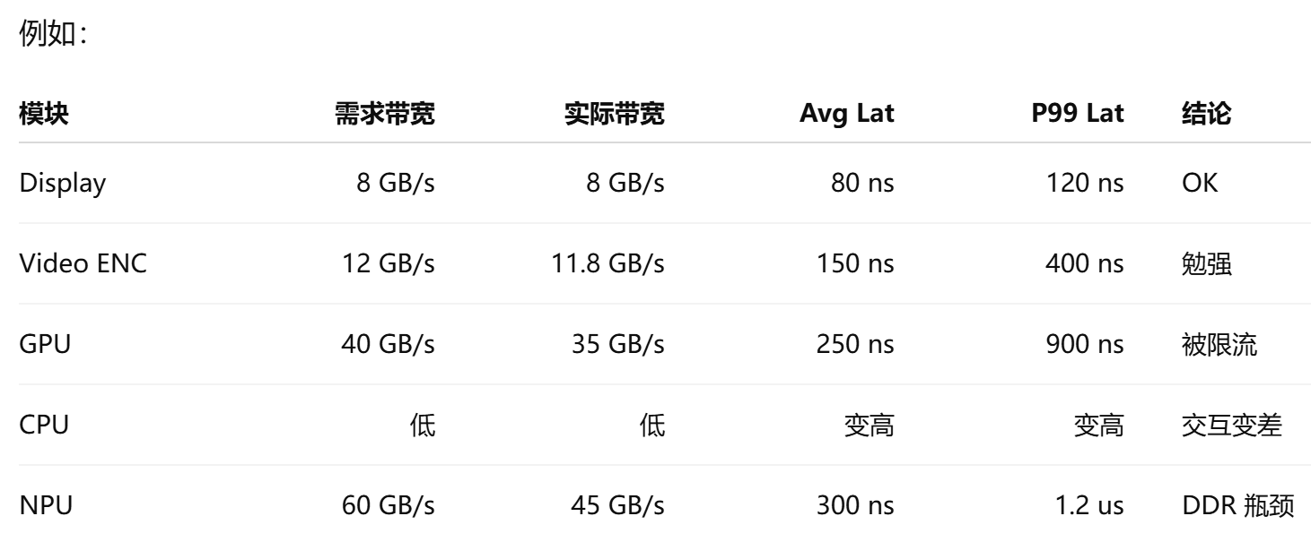 AI Visual Insight: This image illustrates a system-level bandwidth analysis scenario in which multiple masters share internal interconnect and external memory resources. It highlights congestion, queueing latency, and utilization distribution along the path from masters to the NoC and then to the memory controller, making it useful for locating whether the bottleneck sits at the master, interconnect, or DRAM side.
System-level output metrics must cover latency percentiles and congestion location
A mature evaluation result includes far more than “is total bandwidth sufficient?” It should also include achieved bandwidth, average latency, P95/P99 latency, stall cycles, link utilization, queue occupancy, bank conflicts, row hit rate, and whether real-time workloads miss their deadlines.
metrics = {
    "bw": "achieved bandwidth",      # Actual achieved bandwidth
    "lat_p99": "P99 latency",       # Tail latency
    "stall": "stall cycles",        # Stall cycles
    "ddr_util": "DDR utilization"   # DDR channel utilization
}
This code summarizes the core metrics most worth tracking continuously in full-chip interconnect evaluation.
Cost evaluation determines whether a solution is worth implementing
System design must prove not only that something can be built, but also that it is worth building. Cost evaluation does not depend on having complete RTL. In fact, it should be completed early in the HLD phase to reduce project initiation risk.
FPGA resource estimation should prioritize hard resources and historical baselines
Resources such as BRAM/URAM, DSP, SerDes, and PCIe hard IP are usually easier to estimate. The harder part is LUT/FF usage, which should be projected using historical projects, pre-synthesis of similar open-source designs, and scaling based on performance targets.
ASIC area estimation must consider both macro blocks and standard cells
ASIC area estimation should be split into macro blocks such as SRAM and multipliers, and standard-cell logic. SRAM in particular cannot be estimated only by raw bit count. Even for the same 8 Mb capacity, one large block versus a multi-bank architecture can differ significantly in area, power, timing, and routing cost, so repeated back-end-aware exploration is necessary.
Strong system design depends on structured judgment
An excellent digital front-end engineer is not simply someone who writes code faster. It is someone who can complete interface convergence, module decoupling, bottleneck identification, bus modeling, and cost closure before implementation begins. When the system design phase is done correctly, implementation, verification, and production risks all drop significantly.
FAQ
Why should the system design phase define interfaces before partitioning modules?
Because interfaces define the system boundary, the software collaboration model, and the shape of data flow first. If the boundary has not converged, module partitioning is usually only a local optimum and often leads to rework later.
How can you quickly determine whether an accelerator workload is more compute-bound or bandwidth-bound?
Start by calculating Operational Intensity, then analyze it together with DDR/HBM, PCIe, and on-chip buffering capabilities. Low-compute-density workloads are usually bandwidth-limited first, while high-compute-density workloads are usually limited first by parallel compute resources and pipeline depth.
How can FPGA/ASIC cost estimation be done without complete code?
First lock down hard resource requirements, then estimate LUT/FF usage or standard-cell area using historical projects, pre-synthesis, and proportional scaling. The value of early cost estimation is not perfect accuracy, but early exposure of architectural risk.
Core Summary
This article reconstructs the core methodology digital front-end engineers need during the system design phase. It covers interface design, top-level module partitioning, performance bottleneck identification, on-chip bus evaluation, and FPGA/ASIC cost estimation, emphasizing layering, decoupling, measurability, and system-level trade-offs.