This system builds a multi-channel temperature acquisition and closed-loop control pipeline on LabVIEW. Its core capabilities include instrument address parsing, unified sensor management, real-time sampling, and PID temperature regulation, addressing common issues such as device integration chaos, difficult parameter maintenance, and poor temperature-control stability. Keywords: LabVIEW, multi-channel temperature control, PID closed-loop.
Technical Specifications Snapshot
| Parameter | Description |
|---|---|
| Development Language | LabVIEW graphical programming |
| Communication Protocols | Serial, Ethernet, with extensible PLC/NI interfaces |
| Star Count | Not provided in the source |
| Core Dependencies | NI drivers, PID modules, sensor and measurement/control instrument communication libraries |
| Typical Devices | Temperature sensors, measurement and control modules, heating/cooling actuators |
| Target Scenarios | Industrial automation, laboratory constant-temperature systems, equipment retrofits |
The system uses a modular VI architecture to implement the temperature measurement and control loop.
The value of the original design lies not in data acquisition alone, but in breaking the workflow into reusable modules for initialization, addressing, identification, acquisition, control, and display. This approach significantly reduces debugging complexity in multi-channel projects and improves maintainability when scaling to 8, 16, or even more channels.
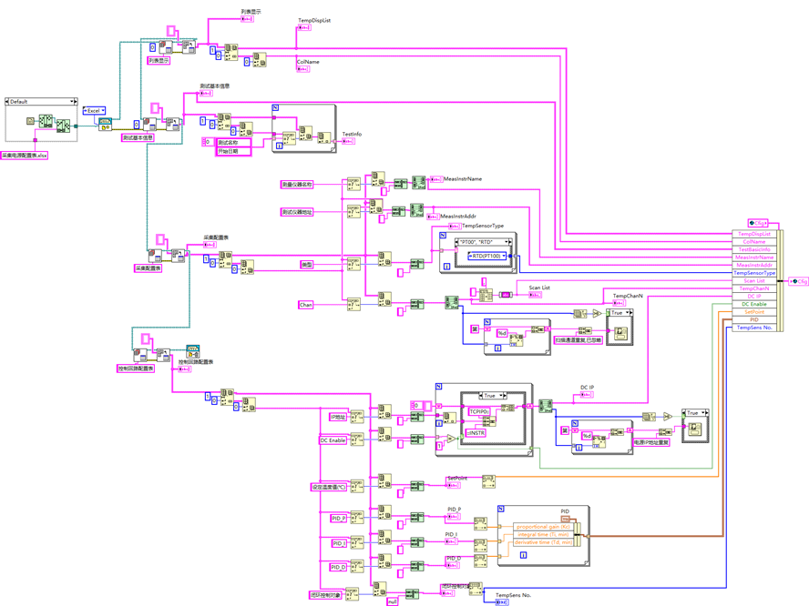
AI Visual Insight: The image shows an overview of a LabVIEW multi-channel temperature control program, likely as a block diagram or front panel. It highlights how modules such as initialization, instrument parsing, temperature acquisition, PID computation, and result visualization connect together, reflecting an implementation centered on dataflow-driven execution, modular chaining, and parallel multi-channel management.
Initialization and device mapping determine whether the system can run reliably.
The basic information initialization VI loads instrument addresses, ports, channel counts, and global parameters. It acts as the startup layer of the system. If configurations are inconsistent at this stage, downstream acquisition and control will encounter chain-level errors.
The address parsing VI maps logical channels to physical hardware, including device IDs, communication IDs, and physical connection paths. In mixed multi-instrument environments, this is the key step that prevents commands from being sent to the wrong device.
class InstrumentConfig:
    def __init__(self, name, address, channel, protocol):
        self.name = name
        self.address = address      # Instrument communication address
        self.channel = channel      # Corresponding temperature channel number
        self.protocol = protocol    # Serial or Ethernet protocol

def build_mapping(configs):
    mapping = {}
    for item in configs:
        mapping[item.channel] = {
            "name": item.name,
            "address": item.address,
            "protocol": item.protocol  # Build the channel-to-device mapping
        }
    return mapping
This code demonstrates the core idea behind a multi-channel instrument mapping table, corresponding to the address parsing and initialization process in LabVIEW.
Instrument name parsing and type identification enable compatibility across multiple devices.
The name parsing VI extracts the model, display name, and log identifier so that the user interface and operational records follow a unified format. In long-running systems, standardized naming reduces misjudgment and shortens manual troubleshooting time.
The type identification VI is even more critical. Different temperature sensors, control modules, and actuators often use different command formats, frame structures, and return units. The system identifies the device type and selects the matching parsing logic, preventing generic workflows from misreading device data.
Sensor list management provides the foundational data structure for multi-channel polling.
The sensor list management VI organizes IDs, addresses, and channel numbers into an iterable collection. This allows upper-layer logic to program against a list instead of duplicating an independent workflow for each channel, resulting in better project scalability.
def poll_temperatures(sensor_list, driver):
    results = []
    for sensor in sensor_list:
        raw = driver.read(sensor["address"])   # Read raw temperature data
        value = round(float(raw), 2)            # Convert to a normalized temperature value
        results.append({
            "channel": sensor["channel"],
            "temp": value
        })
    return results
This code summarizes how to traverse a sensor list and generate standardized output.
Temperature acquisition and PID control together form the system’s core execution pipeline.
The channel parameter configuration VI typically manages the sampling interval, filter strength, precision, and alarm thresholds. In industrial environments, more aggressive settings are not always better. You must balance real-time responsiveness, noise immunity, and control stability.
The temperature data acquisition VI handles raw data reading, parsing, filtering, and format conversion, ultimately outputting normalized temperature values for control computation. It determines the data quality of the control loop and is one of the modules that most needs strong robustness guarantees.
The PID closed-loop module converts temperature error into actuator control output.
The PID closed-loop control VI receives the target temperature, real-time temperature, and P/I/D parameters, then outputs heating, cooling, or power adjustment commands. For systems with large thermal inertia, parameter tuning must avoid overshoot and sustained oscillation.
def pid_step(setpoint, measured, integral, last_error, kp, ki, kd, dt):
    error = setpoint - measured
    integral += error * dt                    # Accumulate historical deviation in the integral term
    derivative = (error - last_error) / dt    # The derivative term reflects the rate of change
    output = kp * error + ki * integral + kd * derivative
    return output, integral, error
This code illustrates the basic calculation logic for PID output in closed-loop temperature control.
The solution delivers clear engineering advantages in industrial temperature control and laboratory scenarios.
In hydraulic test benches, reactors, drying equipment, or laboratory temperature chambers, multiple channels mean higher concurrent acquisition pressure and more complex device organization. A modular VI architecture improves reuse and reduces the refactoring cost when adding new channels.
The source case mentions temperature control for an 8-channel hydraulic test bench with a sampling interval as low as 100 ms and control accuracy of ±0.5°C. This suggests the solution is better suited to small- and medium-scale customized measurement and control projects rather than extremely expensive hard real-time dedicated platforms.
During deployment, prioritize address configuration, filtering, communication bandwidth, and PID tuning.
If address configuration is inaccurate, the system will produce cascading errors during initialization. If filtering is too strong, it will weaken responsiveness. If communication polling is too dense, packet loss and latency may occur. If PID parameters are unreasonable, temperature control will respond too slowly or oscillate.
For that reason, a more reliable deployment sequence is: build the mapping first, validate single-channel behavior next, and perform multi-channel joint debugging last. After tuning is complete, lock down the key parameters to prevent field misoperation from affecting stability.
FAQ
1. Why is it not recommended to implement a multi-channel temperature control system as a single VI?
A single VI is fast to implement when the number of channels is small, but as the device count grows, dataflow, exception handling, and UI logic quickly become tightly coupled, making long-term maintenance difficult. A modular VI architecture is better suited to industrial-scale expansion and reuse.
2. What are the most failure-prone parts of LabVIEW multi-channel temperature control?
The most common issues are instrument address mapping, device type identification, and communication stability. If the address or protocol is interpreted incorrectly, acquisition values become unreliable and PID output loses meaning.
3. What project scale is this solution suitable for?
It is well suited to laboratories, multi-device test benches, and small- to medium-sized industrial automation temperature control projects. If stricter hard real-time performance is required, you can extend this architecture with LabVIEW Real-Time, PLC, or FPGA platforms.
[AI Readability Summary]
This article reconstructs a LabVIEW-based multi-channel temperature measurement and control solution, covering instrument initialization, address and type parsing, sensor list management, temperature acquisition, parameter configuration, and PID closed-loop control. It is suitable for industrial temperature control, laboratory testing, and automation integration.