This article provides a systematic explanation of the most common embedded communication protocols—UART, RS232, RS485, I2C, and SPI. It covers wiring methods, timing rules, electrical characteristics, and typical applications to solve common pain points such as protocol confusion, difficult interface selection, and inefficient debugging. Keywords: embedded communication, I2C, SPI.
Technical Specification Snapshot
| Parameter | Details |
|---|---|
| Domain | Embedded Systems Communication |
| Core Topics | UART, RS232, RS485, I2C, SPI |
| Communication Types | Asynchronous Serial, Synchronous Serial, Differential Bus |
| Typical Languages | C, C++ |
| Typical Protocols/Standards | UART, RS232, RS485, I2C, SPI, Modbus |
| GitHub Stars | Not provided in the source content |
| Core Dependencies | MCU UART controller, GPIO, pull-up resistors, transceiver chips |
The Core Differences Between Serial Protocols Lie in Clocking and Physical-Layer Capability
In embedded systems, data exchange between the main controller and sensors, memory devices, and actuators typically relies on fixed wiring and timing constraints. That is what a communication protocol defines. At the introductory level, the most common protocols fall into two categories: serial interfaces and synchronous bus interfaces.
The serial family is built around UART, while RS232 and RS485 enhance electrical characteristics at the physical layer. I2C and SPI are board-level chip interconnect protocols that emphasize synchronous transfer, short-distance communication, and support for multiple connected devices.
UART Fits the Most Basic Point-to-Point Asynchronous Communication
UART only requires TX, RX, and GND connections to operate. Because the two sides do not share a clock, they must agree in advance on baud rate, data bits, parity, and stop bits. The most common configuration is 8N1: 8 data bits, no parity, and 1 stop bit.
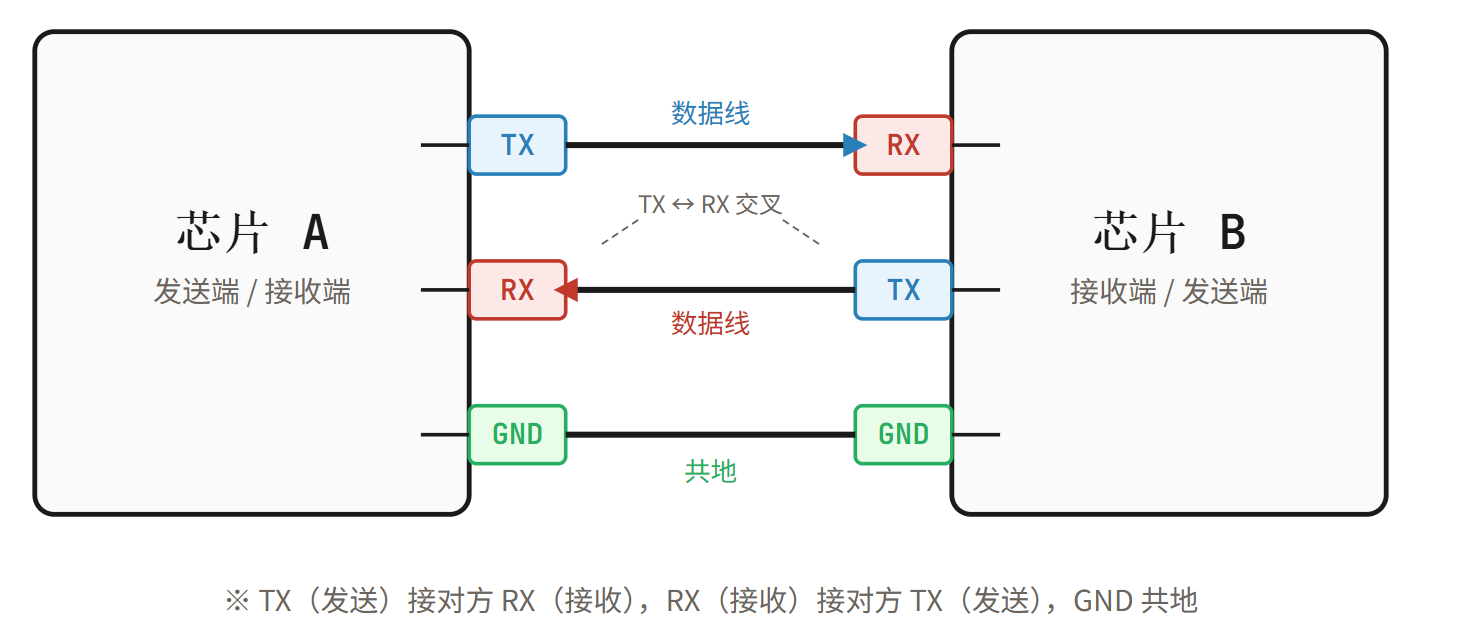 AI Visual Insight: This figure shows the point-to-point UART wiring relationship. The transmitter TX and receiver RX are cross-connected, and a common ground provides a shared reference level, illustrating the minimum hardware loop required for asynchronous serial communication.
UART transfers data frame by frame. The start bit synchronizes the beginning of reception, the data bits carry the payload, and the stop bit marks the end of the frame. Because there is no clock line, UART is simple to implement, but its speed, noise immunity, and communication distance are limited.
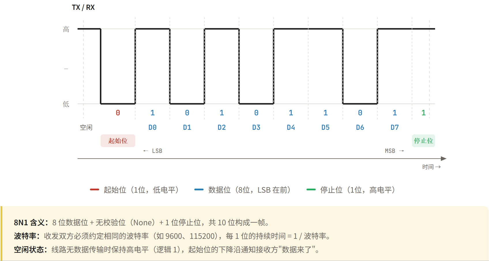 AI Visual Insight: This figure shows the UART frame structure and bit-level timing, including the idle high level, the low start bit, several data bits, and the stop bit. It explains how the receiver reconstructs data at fixed sampling points based on the agreed baud rate.
// Example UART 8N1 configuration
void uart_init(void) {
    baudrate_set(115200);   // Set the baud rate
    data_bits_set(8);       // Set 8 data bits
    parity_set(NONE);       // Disable parity
    stop_bits_set(1);       // Set 1 stop bit
}
This code initializes the most common UART 8N1 communication parameters.
RS232 Enhances the UART Physical Layer Rather Than Replacing It
RS232 is not a new data protocol in essence. It is a specification for serial electrical characteristics. It typically uses relatively high voltages with inverted positive and negative logic levels, so its logic polarity is opposite to TTL serial. As a result, an MCU cannot connect directly to an RS232 device without a level-shifting chip.
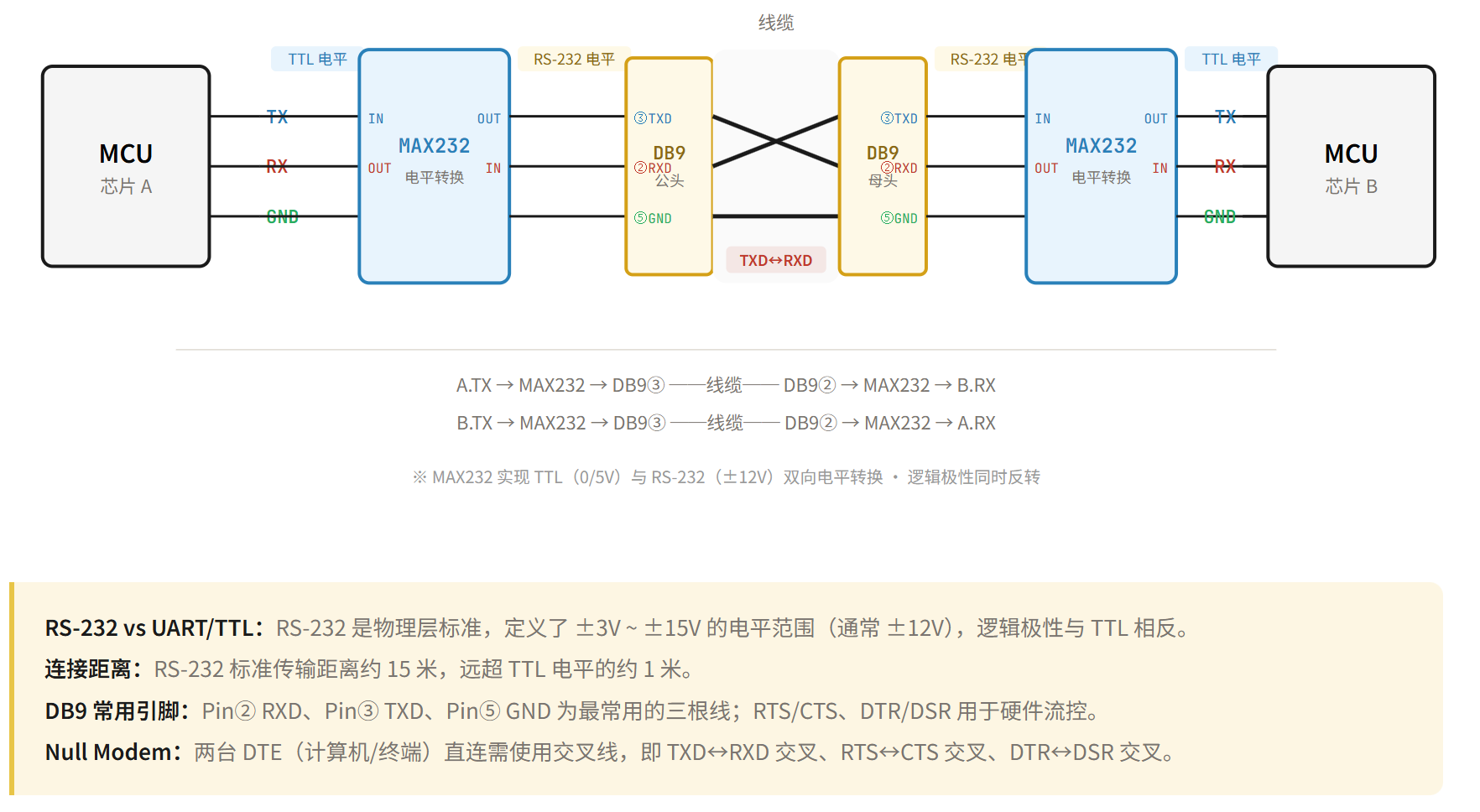 AI Visual Insight: This figure shows a typical RS232 device interconnection. It highlights the point-to-point relationship between the host and the peripheral and emphasizes that the interface layer is usually implemented through a standard serial connector rather than exposed directly at MCU voltage levels.
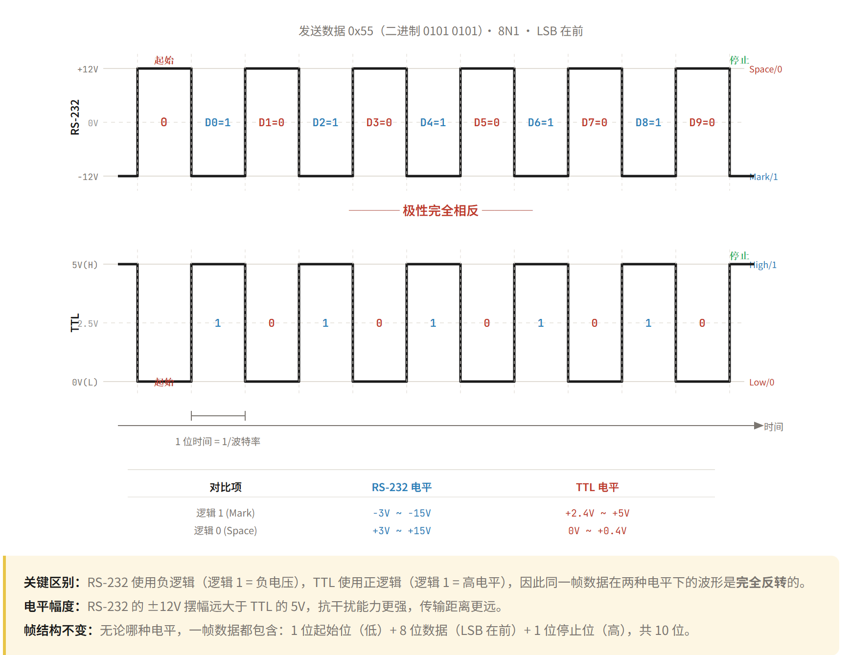 AI Visual Insight: This figure shows RS232 voltage-level timing characteristics, focusing on the polarity difference between RS232 logical “1/0” and TTL serial. It explains why debugging must account for transceivers and signal inversion.
RS232 is common in host-side debugging, legacy industrial equipment, and traditional serial terminals. It is typically used for point-to-point full-duplex communication within about 15 meters. It offers better noise immunity than TTL serial, but it is not suitable for multi-node bus deployment.
RS485 Targets Long-Distance Multi-Node Communication in Industrial Environments
RS485 further strengthens the serial physical layer. Its core feature is differential signaling. The receiver determines logic state from the voltage difference between the A and B lines, making it insensitive to common-mode noise and well suited to complex electromagnetic environments and long cable runs.
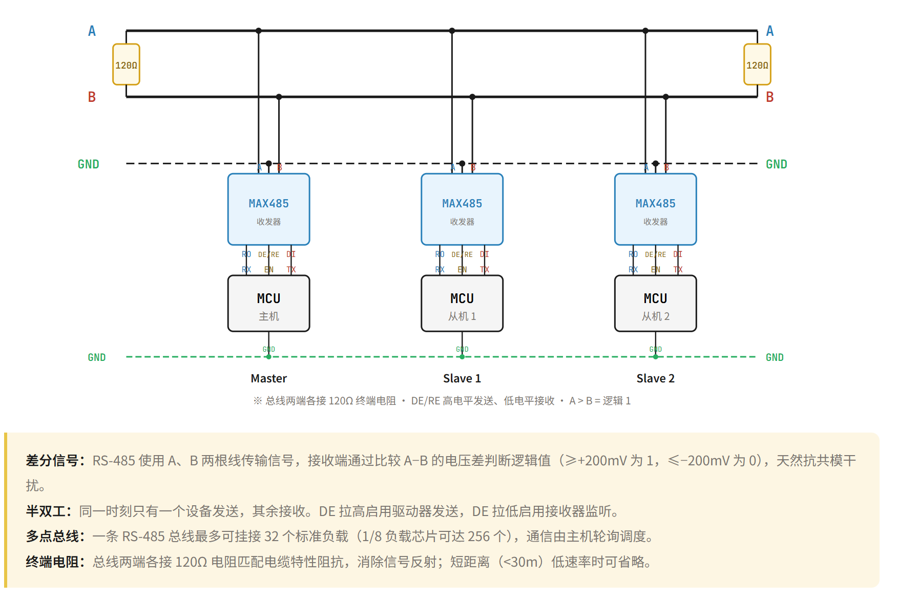 AI Visual Insight: This figure shows the RS485 differential bus topology. Multiple nodes share the same differential pair, highlighting industrial-control characteristics such as bus-style wiring, long-distance transmission, and multiple slave devices on the same network.
RS485 is commonly used in half-duplex mode. Multiple devices can share one bus, but RS485 itself does not define addressing, arbitration, or command formatting. In practice, upper-layer protocols such as Modbus usually provide master-slave communication semantics.
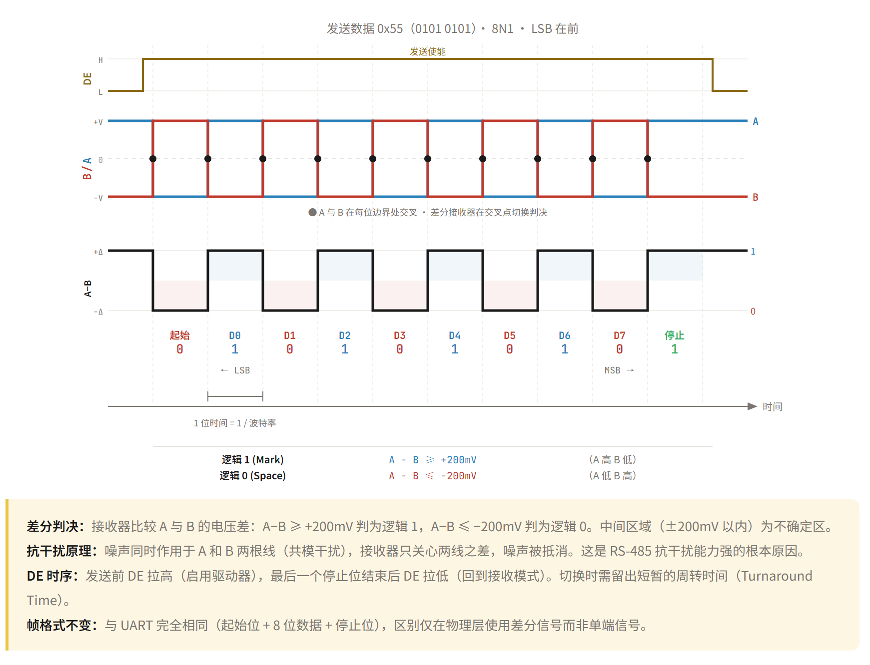 AI Visual Insight: This figure shows RS485 master-slave communication logic and frame interaction flow, illustrating typical bus behavior where the master sends an addressed request, the target slave responds, and non-target nodes remain silent.
// Control transceiver direction before and after RS485 transmission
void rs485_send(uint8_t *buf, int len) {
    gpio_set(DE_PIN, 1);        // Enable transmit mode
    uart_write(buf, len);       // Send data through the UART engine
    uart_wait_tc();             // Wait for transmission complete
    gpio_set(DE_PIN, 0);        // Switch back to receive mode
}
This code demonstrates the direction-control flow used in a half-duplex RS485 scenario.
I2C Enables Multi-Device Board-Level Interconnect With Minimal Pins
I2C uses only two lines, SDA and SCL, to allow one master to communicate with multiple slave devices. It is a synchronous half-duplex protocol in which the master provides the clock and each slave responds based on its address. That makes it ideal for short-distance, low-speed interconnects on the same board.
The key hardware characteristic of I2C is open-drain output. Devices can only drive the bus low and cannot actively drive it high, so both SDA and SCL must rely on pull-up resistors to return to a high level. This is also one of the most common hardware checks during I2C debugging.
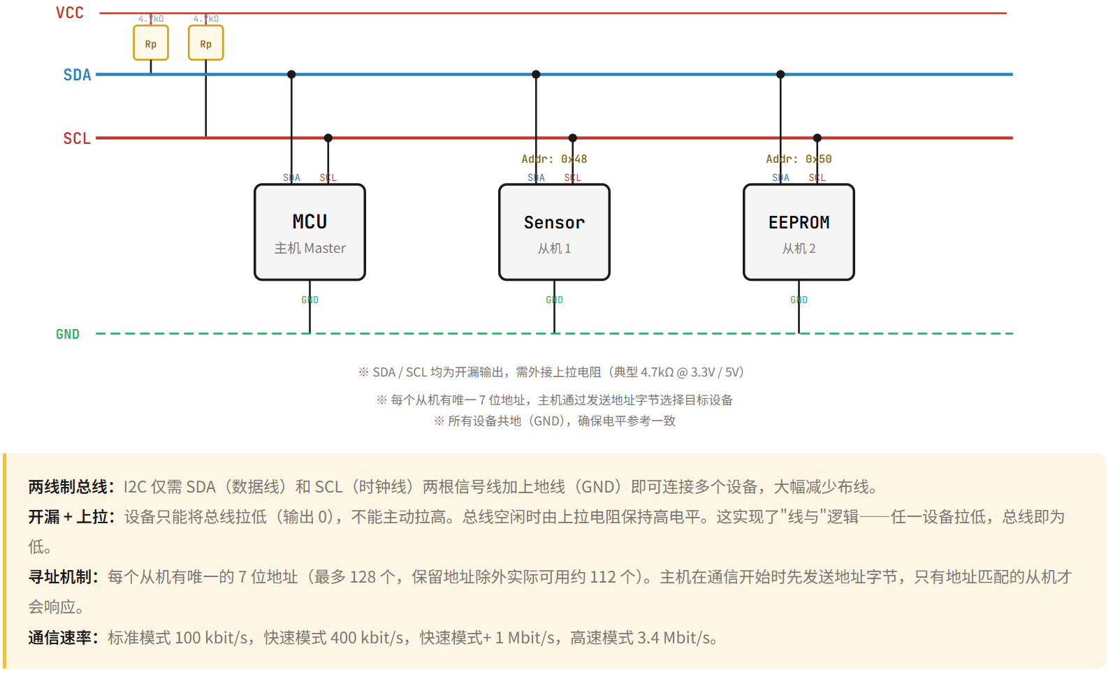 AI Visual Insight: This figure shows the I2C bus open-drain structure and pull-up resistor wiring. Multiple devices share SDA and SCL, while external pull-ups establish the default high level. This is fundamental to understanding ACK behavior, arbitration, and bus release.
The I2C timing rules are strict and explicit: SDA must remain stable while SCL is high; a start condition occurs when SDA transitions from high to low while SCL is high; a stop condition occurs when SDA transitions from low to high while SCL is high. After every 8 bits, there is also 1 ACK bit.
 AI Visual Insight: This figure shows standard I2C bit timing, emphasizing that data must remain stable during the high phase of the clock and may change during the low phase. This is the key basis for analyzing sampling edges and protocol validity.
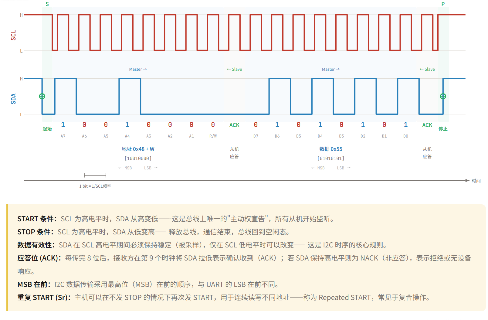 AI Visual Insight: This figure shows the complete frame flow of an I2C write operation, typically including a start condition, 7-bit address, read/write bit, ACK, register address, data byte, and stop condition. It is well suited to register-based driver development.
// Example I2C register write
int i2c_write_reg(uint8_t dev, uint8_t reg, uint8_t data) {
    i2c_start();                 // Send the start condition
    i2c_send_byte(dev << 1);     // Send the device address and write flag
    i2c_wait_ack();              // Wait for slave acknowledgment
    i2c_send_byte(reg);          // Send the register address
    i2c_wait_ack();              // Wait for slave acknowledgment
    i2c_send_byte(data);         // Send the data byte
    i2c_wait_ack();              // Wait for slave acknowledgment
    i2c_stop();                  // Send the stop condition
    return 0;
}
This code summarizes the standard timing sequence for an I2C register write.
SPI Delivers Higher Throughput for High-Speed Peripheral Access
SPI commonly uses a four-wire structure: SCLK, MOSI, MISO, and CS. The master outputs the clock and uses the chip-select signal to choose the target slave precisely, making SPI suitable for high-speed data exchange with low protocol overhead.
Unlike I2C, SPI has no unified addressing mechanism. Expanding to multiple slave devices usually requires additional chip-select lines. Its advantages are simplicity, high speed, and full-duplex communication, which is why it is widely used for Flash memory, displays, network interface chips, and high-speed sensors.
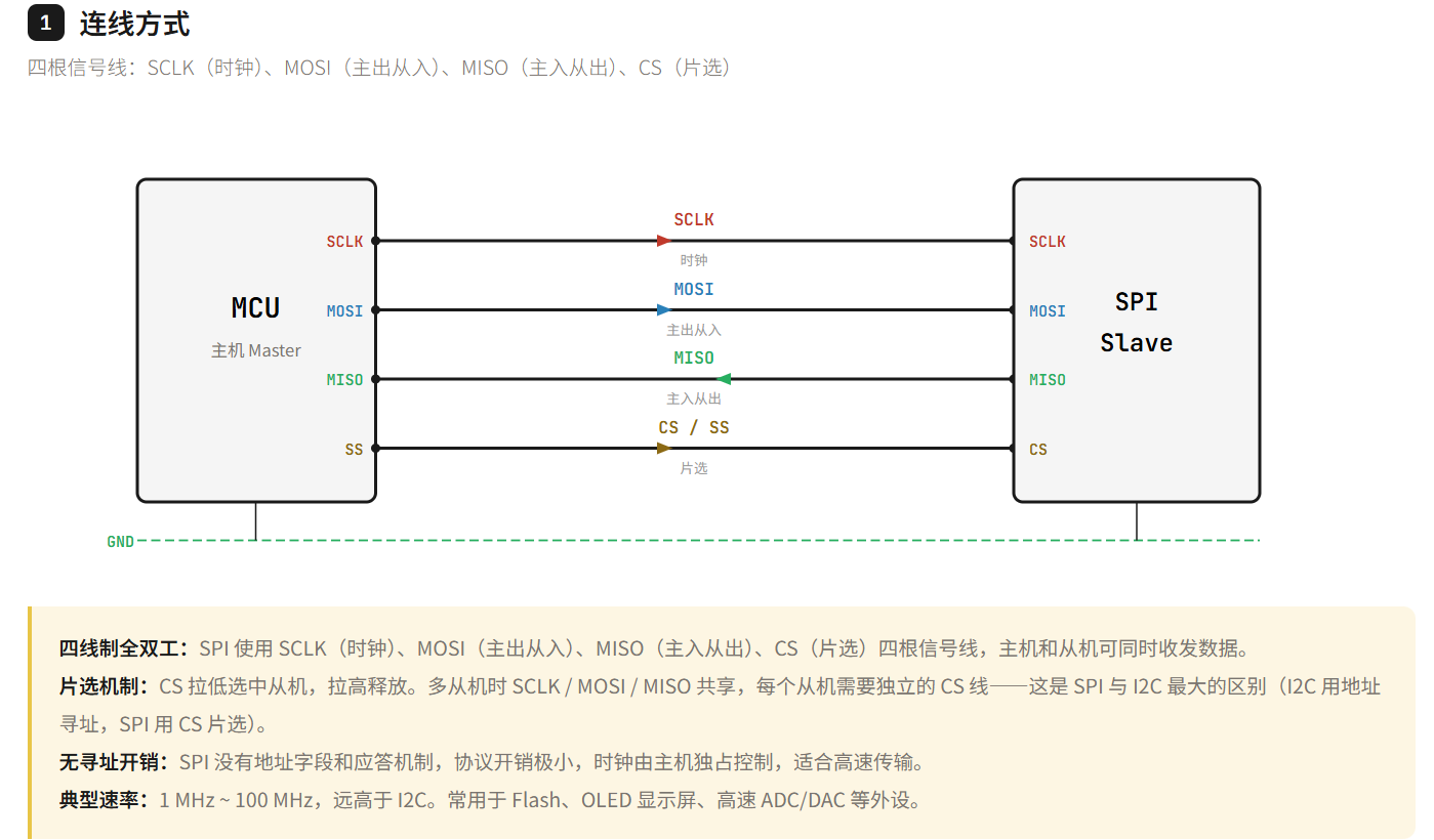 AI Visual Insight: This figure shows the SPI four-wire interconnect structure. The master manages slave devices through dedicated chip-select lines, and separate MOSI/MISO paths enable parallel transmit and receive operation, representing the typical hardware form of high-speed full-duplex communication.
SPI also defines four timing modes, Mode 0 through Mode 3, determined by CPOL and CPHA. If the master and slave use mismatched modes, sampling misalignment, unstable reads, or complete communication failure can occur.
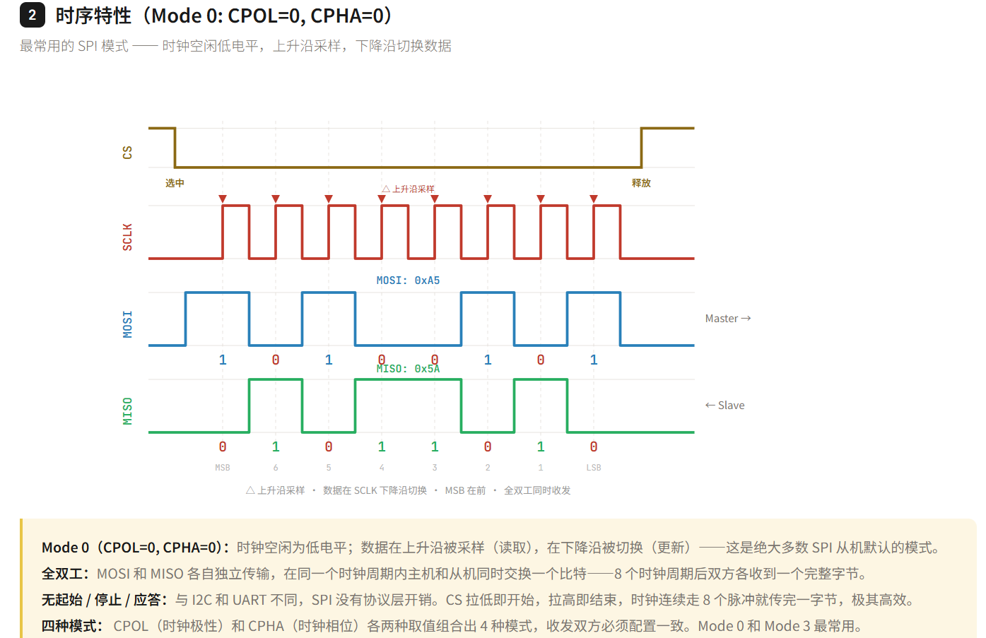 AI Visual Insight: This figure shows how data sampling edges differ under different SPI clock polarity and phase combinations, helping diagnose typical compatibility issues such as “the idle clock level is correct, but the sampling edge is wrong.”
// Example SPI Mode 0 transfer
uint8_t spi_transfer(uint8_t tx) {
    cs_low();                    // Select the slave device
    uint8_t rx = spi_rw(tx);     // Transmit and receive 1 byte synchronously
    cs_high();                   // Release the slave device
    return rx;
}
This code shows the minimum call pattern for a single-byte full-duplex SPI transfer.
Protocol Selection Should Focus on Distance, Speed, Node Count, and Complexity
If your goal is debug logging or simple module communication, choose UART first. If you need to connect to traditional serial equipment, add an RS232 transceiver on top of UART. If the scenario involves industrial environments, multiple nodes, long distances, and strong noise immunity requirements, RS485 is the better fit.
If all devices are on the same board and you want fewer pins, multiple slave devices, and register-oriented access, I2C has clear advantages. If you need to access high-speed memory, display controllers, or any peripheral that demands higher throughput, SPI is usually the first choice.
FAQ
1. What is the relationship between UART, RS232, and RS485?
UART defines the data transfer method, including frame format and asynchronous timing. RS232 and RS485 are physical-layer standards that define voltage levels and transmission media. A common implementation in development is “UART controller + RS232/RS485 transceiver.”
2. Why does I2C require pull-up resistors?
Because I2C SDA and SCL use open-drain outputs, devices can only pull the bus low and cannot actively drive it high. Without pull-up resistors, the bus cannot reliably return to a high level, so start conditions, stop conditions, and ACK signaling will fail.
3. If SPI is faster than I2C, why do many sensors still use I2C?
Because I2C only needs two wires, supports address-based communication, simplifies routing, and reduces cost. It is especially suitable for multiple low-speed peripherals on the same board. SPI is faster, but it usually requires more pins and more chip-select resources.
Core Summary: This article systematically reviews the most common communication protocols in embedded development—UART, RS232, RS485, I2C, and SPI. It focuses on physical layers, electrical characteristics, timing mechanisms, throughput, and applicable scenarios to help developers quickly select the right interface and debug issues efficiently.