This article explains how STM32N6 takes RAW Bayer data from the IMX335, feeds it into ST’s ISP middleware, and produces a color image. The core challenge is that the raw image has color casts, heavy noise, and cannot be used directly. Keywords: STM32N6, IMX335, ISP tuning.
Technical specifications are summarized below
| Parameter | Description |
|---|---|
| Main controller platform | STM32N6570-DK |
| Image sensor | Sony IMX335 |
| Development language | C |
| Image input path | DCMIPP + CSI |
| Image processing path | STM32-MW-ISP |
| Tuning tool | STM32_ISP_IQTune |
| Sensor control bus | I2C |
| Output resolution | 2592 × 1944 |
| Bayer format | RGGB (used in this article) |
| Core dependencies | HAL, DCMIPP, STM32CubeProgrammer, ISP library |
| Stars | Not provided in the original article |
| License | CC 4.0 BY-SA (as stated in the original article) |
This article focuses on moving from “image output works” to “image quality is usable”
The value of STM32N6 is not limited to capturing an image. It can also handle a complete vision pre-processing pipeline on the MCU side. In the previous stage, using DCMIPP to move IMX335 data to the LCD only proved that the pipeline was connected. It did not mean the image quality was usable.
The IMX335 outputs RAW Bayer directly. Without ISP processing, the image usually shows a green or magenta cast, low contrast, and obvious noise. This does not indicate a sensor fault. It simply means the pipeline is missing standard processing stages such as demosaicing, white balance, gamma correction, and noise reduction.
A complete imaging pipeline requires multiple stages to work together
// RAW data can be displayed, but that does not mean the image quality is usable
// A truly usable image requires full ISP pipeline processing
RAW Bayer -> DCMIPP receive -> ISP statistics -> AE/AWB adjustment -> RGB output
This pipeline shows that successful display is only the starting point. Stable imaging becomes possible only after the ISP is involved.
The built-in ISP hardware in STM32N6 significantly lowers the implementation barrier
The key point from the original documentation is that STM32N6 integrates a hardware ISP, and ST also provides the STM32-MW-ISP middleware. As a result, developers do not need to implement complex imaging algorithms from scratch. They only need to connect the sensor control interface to the middleware callbacks.
This shifts the project focus from “building imaging algorithms in-house” to “driver adaptation plus parameter tuning.” For embedded developers, this is a much more practical path to production.
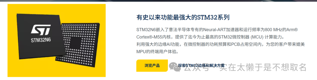 AI Visual Insight: This image shows the STM32N6 development platform, either as hardware or a software interface, to establish the experimental foundation behind the article. Its technical significance is that the ISP, DCMIPP, and later NPU capabilities all run on the same STM32N6570-DK platform, validating that the MCU can handle vision pre-processing locally.
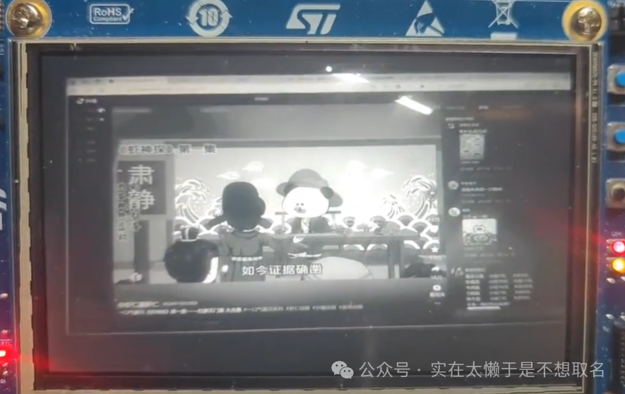 AI Visual Insight: This image shows the raw imaging result before ISP processing. Typical characteristics include color cast, limited tonal detail, and obvious noise. It clearly demonstrates that DCMIPP only receives and moves the pixel stream. It does not automatically perform white balance, demosaicing, or color correction.
STM32_ISP_IQTune is the entry point for image quality tuning
ST provides STM32_ISP_IQTune to modify IQ parameters. Developers first flash the official ISP example program to the development board, connect the board to a PC over USB, and then load the recommended configuration in IQTune for live adjustment.
Unless you are doing dedicated image quality optimization, do not reset the parameters from scratch. A safer approach is to start from the official default configuration and fine-tune black level, AWB, gamma, sharpening, and noise reduction one item at a time.
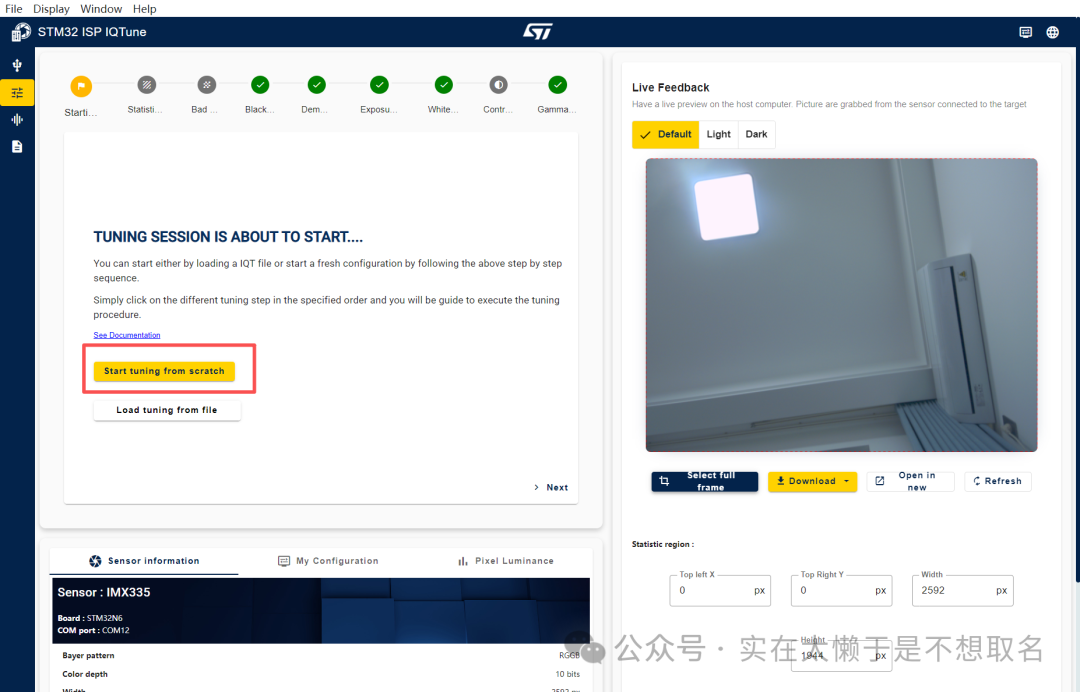 AI Visual Insight: This image shows the main STM32_ISP_IQTune interface or one of its functional pages, illustrating that ST already provides a visual ISP tuning tool. Its main value is that it decouples complex IQ parameters from static code and turns them into an interactive tuning workflow.
 AI Visual Insight: This interface reflects the multi-dimensional nature of ISP parameter tuning and typically includes modules such as exposure, white balance, color matrix, and gamma. It shows that the STM32N6 ISP is not a simple filter. It exposes a parameter system much closer to a professional camera pipeline.
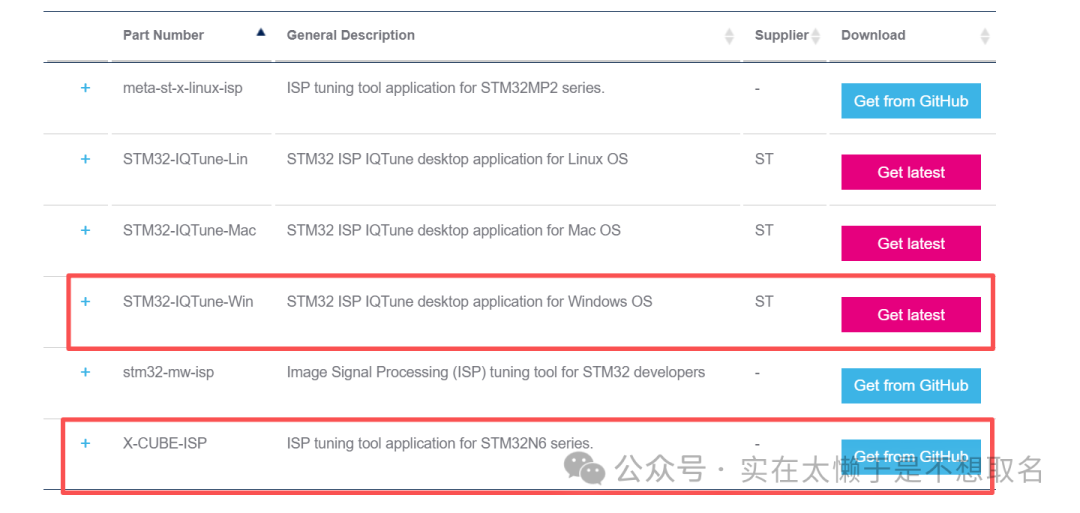
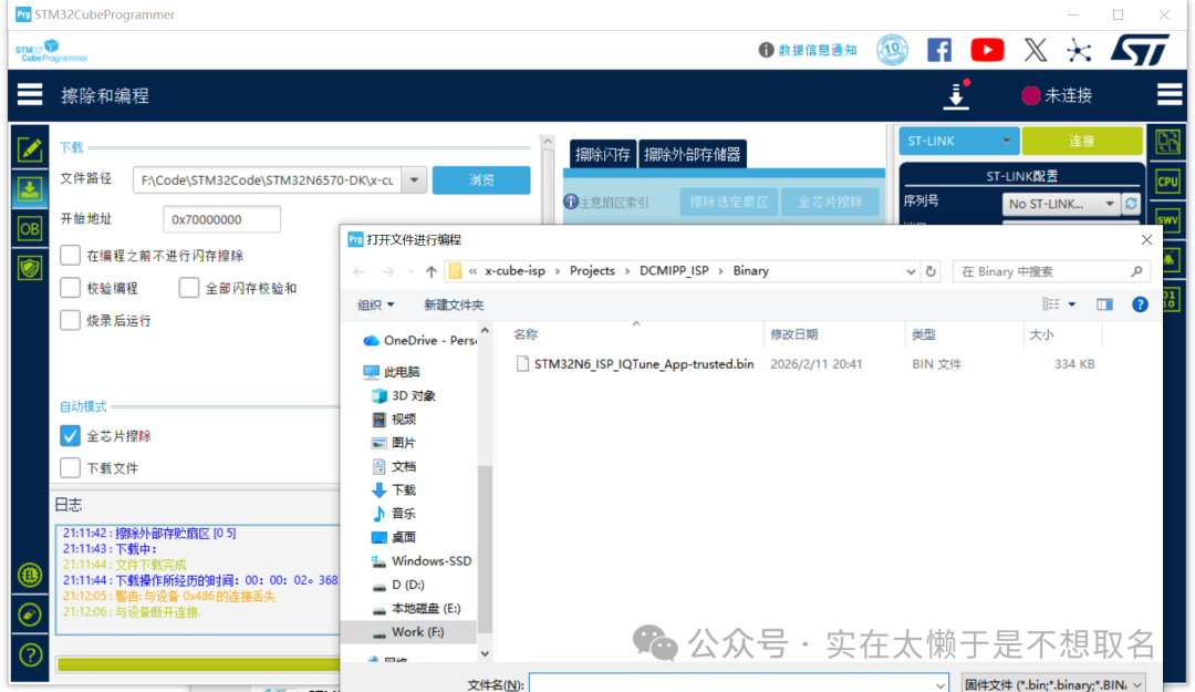 AI Visual Insight: This image shows where to download the tool and related resources, indicating that ISP tuning requires cooperation between PC-side software and board-side firmware. From a technical perspective, this step closes the loop among the tuning tool, target board, and sensor.
The tuning result must be exported as a header file and compiled into the firmware
// Parameters exported by IQTune are usually converted into a .h file
// They are then loaded as the default IQ parameters during ISP_Init
extern const uint8_t ISP_IQParamCacheInit[][ISP_TUNING_PARAMETER_SIZE];
This step bakes the tuned ISP configuration into the firmware so the system can run offline.
The sensor driver must first provide basic control capabilities
Before integrating the ISP, the IMX335 driver must at least support initialization, ID readout, gain setting, exposure setting, frame rate configuration, mirror/flip control, and test pattern output. These are not optional extras. They are the execution endpoints for the ISP automatic control loop.
Many AE, AGC, and AWB decisions must eventually be applied to sensor registers. Without these interfaces, the middleware can only collect statistics and cannot perform feedback control.
int32_t IMX335_Init(I2C_HandleTypeDef *hi2c, uint16_t DevAddr);
int32_t IMX335_SetGain(I2C_HandleTypeDef *hi2c, uint16_t DevAddr, int32_t gain);      // Set analog gain
int32_t IMX335_SetExposure(I2C_HandleTypeDef *hi2c, uint16_t DevAddr, int32_t exposure); // Set exposure time
int32_t IMX335_GetSensorInfo(IMX335_SensorInfo_t *Info); // Get resolution and Bayer information
This group of interfaces defines the minimum sensor control surface that the ISP middleware can call.
The ISP middleware takes over sensor capabilities through callback functions
The key integration method is to wrap the IMX335 driver as helper callbacks defined by the ISP. These include retrieving the sensor name, Bayer pattern, bit depth, resolution, gain range, exposure range, and setting or reading the current exposure and gain values.
This design allows STM32-MW-ISP to remain unaware of IMX335 register-level details. It only needs to call a unified interface to complete automatic control.
ISP_StatusTypeDef SetSensorExposureHelper(uint32_t Instance, int32_t Exposure)
{
    (void)Instance;
    isp_exposure = Exposure; // Cache the current exposure value in software
    if (IMX335_SetExposure(&hi2c1, IMX335_I2C_ADDRESS, Exposure) != IMX335_OK)
    {
        return ISP_ERR_SENSOREXPOSURE; // Sensor register write failed
    }
    return ISP_OK;
}
This code forwards an ISP exposure control request to the IMX335 driver layer.
The VSYNC callback is the key trigger for the statistics feedback loop
Each time a frame is received, DCMIPP triggers a VSYNC-related callback. This callback does more than update the frame count. It also calls ISP_GatherStatistics to collect brightness, color, and other statistics for the AE and AWB algorithms.
void HAL_DCMIPP_PIPE_VsyncEventCallback(DCMIPP_HandleTypeDef *hdcmipp, uint32_t Pipe)
{
    UNUSED(hdcmipp);
    if (Pipe == DCMIPP_PIPE1)
    {
        ISP_IncMainFrameId(&hcamera_isp);   // Update the main frame counter
        ISP_GatherStatistics(&hcamera_isp); // Collect statistics for this frame
        NbMainFrames++;                     // Increment the software frame counter
    }
}
This code gives the ISP a real frame-stream input foundation for automatic tuning.
The ISP initialization process determines whether the full vision pipeline closes the loop
Initialization must complete three tasks: populate the callback functions, configure the statistics area, and start the DCMIPP pipe and the ISP. In the original article, the statistics area directly covers the full 2592×1944 frame, which means AE and AWB evaluate the entire image.
The program then accumulates about 60 frames in the background so the ISP statistics can converge. This phase is similar to the automatic stabilization period after a camera powers on. The first few frames may fluctuate, and the image gradually becomes normal afterward.
void DCMIPP_ISP_Init(void)
{
    ISP_AppliHelpersTypeDef appliHelpers = {0};
    ISP_StatAreaTypeDef statArea = {0};

    appliHelpers.GetSensorInfo = GetSensorInfoHelper;
    appliHelpers.SetSensorGain = SetSensorGainHelper;
    appliHelpers.GetSensorGain = GetSensorGainHelper;
    appliHelpers.SetSensorExposure = SetSensorExposureHelper;
    appliHelpers.GetSensorExposure = GetSensorExposureHelper;

    statArea.X0 = 0;
    statArea.Y0 = 0;
    statArea.XSize = 2592; // Full-frame statistics width
    statArea.YSize = 1944; // Full-frame statistics height

    ISP_Init(&hcamera_isp, &hdcmipp, 0, &appliHelpers, &statArea, ISP_IQParamCacheInit[0]);
    HAL_DCMIPP_CSI_PIPE_Start(&hdcmipp, DCMIPP_PIPE1, DCMIPP_VIRTUAL_CHANNEL0,
                              (uint8_t *)lcd_bg_buffer, DCMIPP_MODE_CONTINUOUS);
    ISP_Start(&hcamera_isp);
}
This code completes the core initialization sequence from middleware registration to video stream startup.
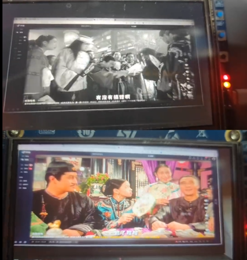 AI Visual Insight: This image shows the final imaging result after the ISP starts. The image has typically completed color restoration, contrast enhancement, and noise suppression. It proves that STM32N6 has implemented a closed-loop vision pipeline consisting of sensor capture, statistical analysis, parameter feedback, and color output.
The current result is already usable, but professional image quality still depends on IQ parameters
The original article ends by emphasizing that default parameters can only move the image from “unusable” to “acceptable.” What truly defines the upper limit of image quality is continuous iteration in IQTune, especially for black level, demosaicing, white balance reference points, gamma curves, noise reduction, and sharpening strategy.
For embedded vision projects, this stage often takes more time than basic interface bring-up, but it is also much closer to product-grade quality. At this point, STM32N6 is no longer just moving image data. It has gained control over the imaging pipeline itself.
FAQ
Q1: Why does the image still look green or magenta even though IMX335 is already outputting frames?
A: Because the display is showing RAW Bayer data that has not yet gone through demosaicing, AWB, CCM, gamma correction, and noise reduction. DCMIPP handles capture, but it does not perform the full ISP imaging pipeline.
Q2: What are the most critical interfaces when integrating a sensor with STM32-MW-ISP?
A: The key interfaces are the helper callbacks for reading sensor information, setting and reading gain, and setting and reading exposure. Without them, automatic controls such as AE and AGC cannot form a closed loop.
Q3: Why do you still need to wait for about 60 frames after initialization?
A: Because the ISP needs statistics from consecutive frames to converge exposure and white balance parameters. The first few frames are only sampling. As the statistics accumulate, the image gradually stabilizes.
Core summary
This article reconstructs the key integration path for driving IMX335 with STM32N6. It focuses on the coordinated use of DCMIPP, STM32-MW-ISP, and STM32_ISP_IQTune, and explains how to connect sensor information, implement exposure and gain control, collect VSYNC-based statistics, and start the ISP so RAW Bayer images become tunable color output.