[AI Readability Summary] This workflow automates signal-based DTC testing for automotive CAN bus systems. By importing a DBC file, the tool generates an Excel communication matrix, signal fault test cases, CANoe simulation nodes, and XML diagnostic configuration. It reduces repetitive scripting, centralizes configuration, and improves integration efficiency. Keywords: DBC parsing, DTC testing, CANoe simulation.
The technical specification snapshot defines the toolchain at a glance
| Parameter | Description |
|---|---|
| Target scenario | Automated signal-based DTC testing for automotive CAN bus systems |
| Input files | .dbc, preconfigured .xlsx |
| Output files | Excel communication matrix, .can, .xml |
| Runtime mode | GUI tool with Auto_Dtc_Can.exe as the entry point |
| Related platform | CANoe |
| Core protocols | CAN, diagnostic request ID / response ID binding |
| Primary languages | Python, CAPL (for generated output integration) |
| Core dependencies | DBC database, Excel configuration, CANoe project |
| GitHub stars | Not provided in the source |
The core value of this tool is that it turns repetitive DTC script development into a configuration-driven workflow
In traditional projects, signal invalidation, signal loss, Rolling Counter faults, and Checksum faults often require test engineers to write CAPL or supporting scripts one case at a time. The real pain point is not technical complexity. It is repetitive work at scale.
The design is straightforward: use the DBC as the single source of truth, capture test-specific differences in Excel configuration, and then automatically generate test cases, simulation nodes, and XML. This approach reduces manual coding and makes test assets reusable.
The output artifacts have clear responsibilities
- Excel stores the communication matrix and DTC configuration.
.canstores the simulation node logic..xmlstores the test configuration for diagnostic request ID and response ID binding.- CANoe serves as the final execution and validation platform.
# Pseudocode: core automation workflow
from pathlib import Path

# Read the DBC and export the communication matrix  # Core input source
source_dbc = Path("input/network.dbc")
excel_file = export_matrix_from_dbc(source_dbc)

# Manually complete DTC and fault trigger rules in Excel  # Configuration-driven test behavior
configured_excel = fill_dtc_rules(excel_file)

# Generate the simulation node and XML  # Integrate with the CANoe execution environment
can_file = build_simulation_node(configured_excel)
xml_file = build_diag_xml(configured_excel, req_id="0x700", res_id="0x708")
This code captures the essence of the solution: the DBC defines structure, Excel defines test intent, and CAN/XML define the execution artifacts.
The complete operating procedure can be broken down into seven stable steps
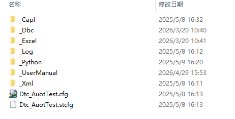
The first step is to launch the tool. Enter the _Python directory and run Auto_Dtc_Can.exe. This indicates that the developer has already packaged the complex dependencies into an executable, which lowers the barrier for frontline test engineers.
The second step is to load the DBC. The user only needs to select the target .dbc file in the GUI. The tool then reads message, signal, and node information as the base data for all subsequent export and generation tasks.
Moving from DBC to Excel is the turning point of the entire workflow
The third step is to generate the Excel communication matrix. It is recommended to save the file in the _Excel directory and keep the filename aligned with the DBC filename. This is not just stylistic consistency. It simplifies version tracking and reverse lookup.
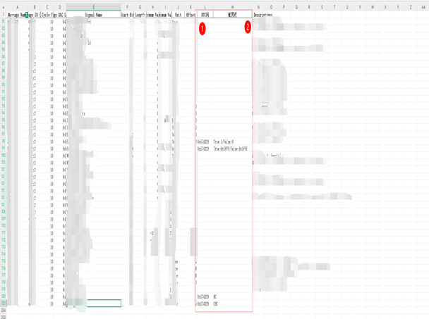
The fourth step is the key configuration stage. Test engineers must complete the DTC codes and trigger rules in Excel. The format of this configuration directly determines whether the generated output will be reliable.
Example DTC configuration rules
- Single DTC: 0x574D29
- Multiple DTCs: 0x574D29/0x574E29
- Signal type: True:1/False:0
- Signal type (hex): True:0x1FFF/False:0x1FFE
- RollingCounter type: RC
- Checksum type: CRC
These rules define how a fault is triggered, how it recovers, and which fault category it belongs to.
Simulation node and XML generation make the workflow executable rather than static
The fifth step is to optionally generate the .can file. If the only goal is to build the simulation node, this step is sufficient. However, it does not directly generate DTC test cases, so in most cases you still need to read the Excel file back in.
The sixth step is to read the Excel file back and populate the .can file. This means the simulation node is not just a static template. It generates concrete behavior based on the configured signal rules. Save the generated .can file in the _Capl directory and replace the original file directly.
Diagnostic binding configuration determines whether the test chain is truly closed-loop
The seventh step is to generate the XML file. The user must enter the diagnostic request ID and response ID in hexadecimal format. Then select the fully configured Excel file, export the XML to the _Xml directory, and overwrite the original file.
<!-- Example: diagnostic communication binding configuration; field names are illustrative -->
<DiagnosticConfig>
  <RequestId value="0x700" />
  <ResponseId value="0x708" />
  <Source file="configured_matrix.xlsx" />
  <Mode value="DTC_Auto_Test" />
</DiagnosticConfig>
This XML shows that the test execution layer now has the diagnostic request mapping, response mapping, and configuration source it needs.
CANoe project integration must follow explicit loading and initialization principles
Even after the tool generates .can and .xml, the CANoe side still requires you to manually load the corresponding DBC. The reason is simple: without the database binding, messages and signals cannot be interpreted correctly, and the generated scripts lose their semantic foundation.
In addition, you must enable the Init test case before running the test. In many cases where the script looks correct but execution fails, the root cause is not the code itself. The environment was never initialized, so timers, channels, diagnostic context, or node state became inconsistent.
The four most common pitfalls are easy to avoid
- Do not rename the generated
.canand.xmlfiles. Overwrite the files in their original paths. - Back up the DBC before parsing, then remove the node under test from the backup, or suppress its transmission in the
.canfile. - The CANoe project must bind the corresponding DBC. Otherwise, signal parsing will fail.
- Always enable the Init test case before execution to ensure a consistent environment.
These screenshots show that the tool has reached an engineering-ready form
 AI Visual Insight: This screenshot shows the main GUI or entry function area. It highlights that DBC selection, Excel generation,
 .can generation, and XML export have been consolidated into graphical buttons, which indicates that the tool has evolved from script-level automation into an interactive application for test engineers.
 AI Visual Insight: This screenshot most likely shows the Excel communication matrix or configuration interface. From a technical perspective, the focus is the mapping between signal names, DTC codes, and configuration fields. It reflects the transformation from structured database information into structured test-rule configuration.
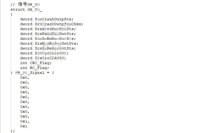
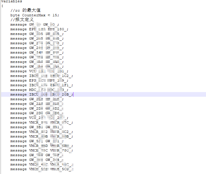 AI Visual Insight: This image likely shows generated
 .can output or CAPL-related artifacts. Its technical value lies in confirming that the automation tool does more than export a checklist. It can also produce executable simulation node logic that supports fault injection, signal invalidation simulation, and regression testing.
 AI Visual Insight: This screenshot appears closer to an XML or project integration configuration view. It shows that the tool supports structured binding between diagnostic request IDs, response IDs, and test items, giving the CANoe automation execution chain a clear configuration entry point and better maintainability.
This approach is well suited for Tier 1 teams that want standardized test asset accumulation
From an efficiency standpoint, work that previously required a full day of repetitive scripting can be compressed into roughly ten minutes. More importantly, the outputs follow a uniform format, which improves team collaboration, issue reproduction, and version management.
From an engineering standpoint, this is not just a local scripting improvement. It creates a closed loop that connects the DBC, diagnostic configuration, simulation logic, and execution platform. That makes it especially valuable for chassis, body, powertrain, and domain controller projects.
FAQ
1. Why can CANoe still not parse signals correctly after the .can file is generated?
Because the .can file is only the execution script or simulation node. Signal semantics still depend on the DBC. If the CANoe project does not load the corresponding DBC, messages may still exist, but signals cannot be parsed in a structured way.
2. What does True:value/False:value mean in Excel?
It defines the fault trigger value and the fault recovery value. True is the signal value written when the fault is triggered, and False is the value written when normal communication is restored. This is a core configuration item for automatically generating signal-based DTC tests.
3. Why is it recommended to back up the DBC and remove the node under test?
If the node under test continues to transmit in the original project, it may conflict with the auto-generated simulation node. That can cause bus contention, signal overwrites, or failed fault injection, which reduces the credibility of the test results.
Core takeaway: This article reconstructs a practical DTC automation solution for automotive CAN bus systems. It covers DBC parsing, Excel communication matrix export, signal fault test case generation, CANoe simulation node .can generation, and XML configuration binding. It is well suited for Tier 1 suppliers and automotive test engineers who want to deploy a repeatable workflow quickly.