This article focuses on the
udp_payload_appendmodule and explains how to use Design Compiler to complete RTL synthesis, generate a netlist and SDF, and run both RTL and gate-level post-synthesis simulation in ModelSim. It addresses a common pain point: a full UDP project is too heavy for beginners to use directly for ASIC synthesis. Keywords: Design Compiler, gate-level simulation, UDP.
The technical specification snapshot is concise and practical
| Parameter | Details |
|---|---|
| Language | Verilog, Tcl, Shell |
| Synthesis Tool | Synopsys Design Compiler |
| Simulation Tool | ModelSim / Questa |
| Protocol Context | UDP payload data processing |
| Process Library | TSMC18 typical.db, tsmc18.v |
| Clock Constraint | 10 ns, 100 MHz |
| Appended String | \nnihaoya,dongwazi~ |
| Article Popularity | Original post: about 380 views, 9 likes, 8 bookmarks |
This experiment uses a small module that is well suited for synthesis
The original project comes from an Ethernet UDP design, but the full system includes RGMII/GMII, ARP, ICMP, UDP, PLL, asynchronous FIFO, and vendor IP. That makes it unfriendly for direct ASIC synthesis practice. To reduce complexity, this experiment extracts only udp_payload_append as a standalone target.
This module has clear boundaries and does not depend on FPGA-specific primitives. It captures the complete flow of synthesis, constraints, netlist generation, and SDF back-annotation, while keeping verification focused on the data path and control timing.
 AI Visual Insight: The figure shows where this experiment target sits inside the original UDP system. It highlights that the module is placed between payload reception and the downstream transmit path, where it handles data buffering, fixed-string appending, and transmit-start control. This makes it a typical local data-path control unit.
The module behavior can be defined precisely
On the input side, the module receives rec_en, rec_data, rec_pkt_done, and rec_byte_num. When payload data arrives, it writes bytes into a FIFO. After a packet ends, it automatically writes an additional fixed 18-byte string and then emits a tx_start_en pulse.
If the input is HELLO with a length of 5 bytes, the final output should be HELLO\nnihaoya,dongwazi~, so tx_byte_num must equal 23. This makes the simulation pass criteria very explicit.
localparam [15:0] APPEND_LEN_16 = 16'd18;
localparam [5:0]  APPEND_LAST   = 6'd17;

// Return the appended character by index
function [7:0] append_byte;
input [5:0] idx;
begin
    case (idx)
        6'd0 : append_byte = 8'h0A; // Newline
        6'd1 : append_byte = 8'h6E; // n
        6'd17: append_byte = 8'h7E; // ~
        default: append_byte = 8'h00;
    endcase
end
endfunction
This code block encodes the fixed appended string as synthesizable lookup logic.
Constraints and scripts define the synthesis target together
The constraint file contains only a few core items: create a 100 MHz clock, set 0.2 ns clock uncertainty, mark the asynchronous reset as a false path, add I/O delays, and set load and fanout. For an introductory experiment, this already covers the most basic timing environment.
set CLK_PERIOD 10.0
create_clock -name clk -period $CLK_PERIOD [get_ports clk]
set_clock_uncertainty 0.2 [get_clocks clk]
set_false_path -from [get_ports rst_n]  ;# Do not apply normal timing analysis to the asynchronous reset
set_input_delay 1.0 -clock [get_clocks clk] \
  [remove_from_collection [all_inputs] [get_ports {clk rst_n}]]
set_output_delay 1.0 -clock [get_clocks clk] [all_outputs]
This code block gives DC a realistic but simplified timing world to drive synthesis optimization.
run_dc.tcl is the hub of the automation flow
The script performs five tasks: set paths, load typical.db, read the RTL, load constraints and run compile, then write out the netlist and reports. In essence, it turns a manual point-and-click flow into a reproducible script.
set_app_var target_library [list typical.db]    ;# Specify the target standard-cell library
set_app_var link_library   [list * typical.db]  ;# Specify the link library
analyze   -format verilog "$RTL_DIR/udp_payload_append.v"
elaborate $DESIGN_NAME
link
compile -map_effort medium -area_effort medium  ;# Run medium-effort optimization
write -format verilog -hierarchy -output "$NET_DIR/${DESIGN_NAME}_syn.v"
write_sdf "$NET_DIR/${DESIGN_NAME}.sdf"
This code block maps the RTL into the standard-cell library and exports the artifacts required for gate-level verification.
The directory structure makes synthesis and simulation results traceable
The project is organized into rtl/, constraint/, dc/, sim/, netlist/, report/, and lib/. This structure naturally separates source files, constraints, scripts, netlists, logs, and library files, making the experiment easier to reproduce and debug.
A single command can run the full synthesis flow
cd ~/dc_udp_payload_lab/dc
# Run Design Compiler synthesis and save the terminal output to a log file
 dc_shell-t -f run_dc.tcl | tee ../report/dc_run.log

# Quickly inspect timing and constraint status
grep -i "slack" ../report/timing.rpt | head
grep -i "violated" ../report/constraint.rpt
This code block runs synthesis and quickly checks whether the design meets timing and constraint requirements.
If the report shows slack (MET) with positive slack, and also reports There are no violated constraints., then the module has passed the basic synthesis checks under the current process library and constraints.
RTL pre-simulation confirms that the intended logic is correct
RTL simulation works directly on the source code. Its goal is not to verify process delay, but to verify functionality: whether the design writes 23 bytes, whether tx_byte_num equals 23, whether des_mac/des_ip pass through correctly, and whether tx_start_en asserts for one cycle as expected.
// Capture FIFO output on the falling clock edge for byte-by-byte comparison
always @(negedge clk) begin
    if(!rst_n) begin
        wr_count = 0;
    end else if(wr_fifo_en) begin
        captured[wr_count] = wr_fifo_data; // Record each emitted byte
        wr_count = wr_count + 1;
    end
end
This code block stores the byte sequence emitted by the DUT so it can be compared automatically against the expected string.
The strongest proof of simulation success is byte-for-byte equality
The testbench does not rely only on TEST PASSED!. It also compares all 23 bytes one by one against HELLO plus the appended string. This check is more robust than simply inspecting waveforms because it turns the functional requirement into an executable assertion.
Gate-level post-synthesis simulation verifies that synthesis preserved functionality
In post-synthesis simulation, the DUT changes to udp_payload_append_syn.v, and udp_payload_append.sdf is loaded as well. At this stage, ModelSim also needs tsmc18.v because the synthesized netlist already contains standard-cell instances such as DFF, INV, and NAND.
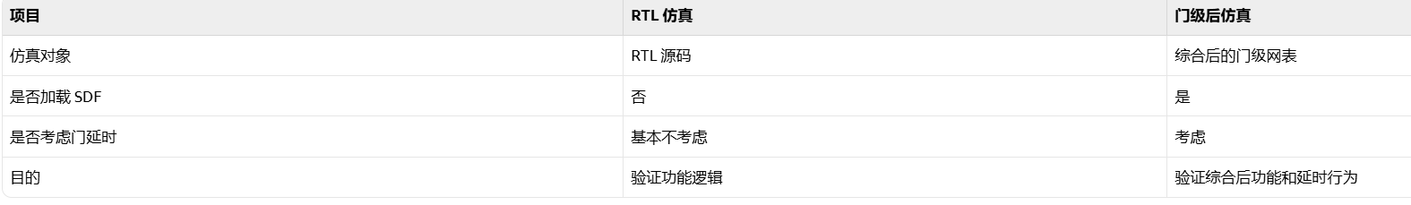 AI Visual Insight: The figure compares the verification scope of RTL simulation and gate-level post-synthesis simulation. The former focuses on logical correctness, while the latter introduces cell delays and SDF back-annotation to observe whether post-synthesis timing behavior still matches the expected functionality.
vlog -work work ../lib/pdk_tsmc18/Verilog/tsmc18.v
vlog -work work ../netlist/udp_payload_append_syn.v
vlog -work work tb_udp_payload_append.v
vsim -voptargs=+acc \
  -sdftyp /tb_udp_payload_append/dut=../netlist/udp_payload_append.sdf \
  work.tb_udp_payload_append
This code block compiles the standard-cell models and synthesized netlist, then back-annotates SDF delays onto the DUT instance.
If the log shows SDF Backannotation Successfully Completed. and the simulation still prints TEST PASSED!, then the synthesized netlist remains behaviorally consistent with the RTL under timing-annotated conditions.
Intermediate states in gate-level waveforms are physical implementation effects, not errors
The original article adds an important observation from a serial-to-parallel conversion experiment: in RTL, a bus update may appear to settle all at once, but in gate-level post-simulation, each register bit can have a slightly different clk-to-q delay. As a result, the bus may briefly show transitional values such as 0440 -> 0C40 -> 2C42, which is normal.
This illustrates that gate-level post-synthesis simulation does not aim to make the waveform “look like RTL.” Its real purpose is to confirm that final functionality, timing relationships, and key pulses still hold. As long as the sampling point is correct, brief intermediate states do not indicate design failure.
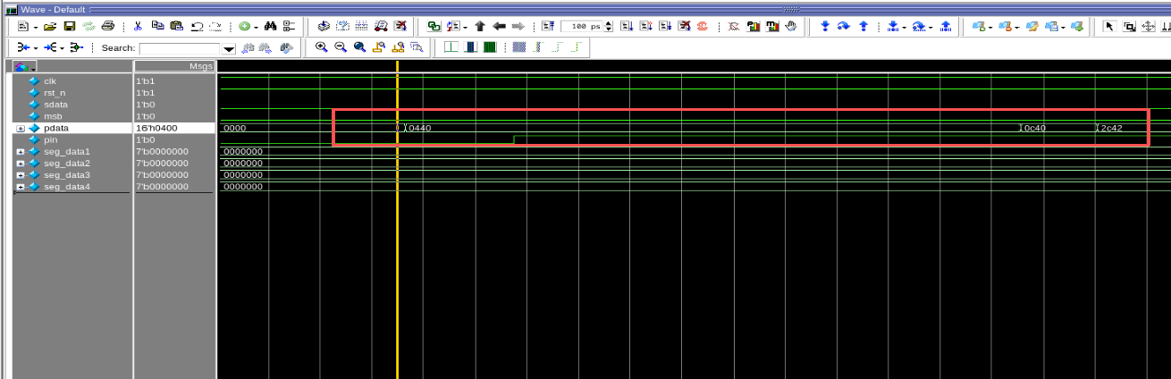 AI Visual Insight: The gate-level waveform in the figure shows the bus passing through multiple transitional encodings before settling to its final value. This reflects propagation-delay differences across flip-flops and combinational paths and is a typical manifestation of real gate-level timing after SDF back-annotation.
This flow works well as an introductory digital IC lab template
Compared with synthesizing a full UDP protocol stack, this case is a lower-coupling and higher-verification-value training example. It closes the loop across RTL coding, constraint modeling, scripted synthesis, report analysis, and pre/post simulation.
For beginners, what matters is not just getting the tools to run, but understanding three evaluation criteria: whether the functionality is correct, whether timing converges, and whether the netlist can be validated through post-synthesis simulation. This module ties all three together.
FAQ provides structured answers to common questions
1. Why not synthesize the entire FPGA UDP project directly?
The full project includes PLLs, asynchronous FIFOs, PHY interfaces, and vendor IP. These increase synthesis complexity and introduce noise unrelated to the ASIC flow. Selecting an independent module keeps the learning path focused on Design Compiler and gate-level verification.
2. What problems do typical.db and tsmc18.v solve respectively?
typical.db is used for synthesis mapping and timing optimization. It determines which standard cells DC can use to implement the logic. tsmc18.v is used for simulation so that ModelSim can understand the behavior of the standard cells instantiated in the synthesized netlist.
3. If gate-level post-simulation shows brief incorrect values, does that mean synthesis failed?
Not necessarily. If the intermediate values appear only during bus transitions, the final sampled values are correct, tx_start_en and the data sequence both pass checking, SDF back-annotation succeeds, and no critical errors appear, then this is usually a normal gate-delay effect.
Core summary: This article uses the udp_payload_append module to rebuild a complete verification chain from RTL, timing constraints, and Design Compiler synthesis to ModelSim gate-level post-synthesis simulation, with emphasis on appended-string logic, SDF back-annotation, timing report interpretation, and gate-level intermediate-state behavior.