The core goal of firewall dual-device hot standby is to make failover invisible to upstream and downstream devices. This article focuses on three routing-mode topologies and explains how VRRP, VGMP, HRP, OSPF, and BFD work together to enable active/standby switchover and session persistence. Keywords: dual-device hot standby, VRRP, VGMP.
Technical Specifications at a Glance
| Parameter | Details |
|---|---|
| Domain | Firewall High Availability / Network Security |
| Operating Mode | Routing Mode |
| Core Protocols | VRRP, VGMP, HRP, OSPF, BFD |
| Neighbor Types | Layer 2 Switches, Layer 3 Routers |
| Typical Vendor Context | Huawei Firewall Dual-Device Hot Standby |
| Primary Goal | Seamless Active/Standby Failover, No Session Interruption |
| Stars | Not provided in the source content |
| Core Dependencies | Heartbeat Link, Session Synchronization, Dynamic Routing or Virtual Gateway |
The Nature of Dual-Device Hot Standby Depends on Neighbor Device Types
Dual-device hot standby is not a single design pattern. It is a mechanism chosen according to the adjacent devices. The goal is always the same: when the primary firewall fails, the standby device takes over forwarding without requiring manual reconfiguration on switches or routers.
Switches and routers make forwarding decisions differently, so they require different failover mechanisms. Layer 2 switches rely on MAC tables and ARP, while Layer 3 routers rely on next hops and routing metrics. That distinction defines the boundaries between VRRP-based designs and dynamic-routing-based designs.
Switches and Routers Use Different Decision Logic
| Device Type | Forwarding Basis | What It Evaluates | Common Failover Method |
|---|---|---|---|
| Layer 2 Switch | MAC Table | Which device responds to gateway ARP | VRRP + Gratuitous ARP |
| Layer 3 Router | Routing Table | Which device is the better next hop | OSPF/BGP/BFD |
# Core idea in a switch-based scenario: provide a stable virtual gateway
interface GigabitEthernet1/0/1.10
 vlan-type dot1q 10
 ip address 192.168.10.2 24
 vrrp vrid 10 virtual-ip 192.168.10.1  # Virtual gateway IP remains unchanged
This configuration provides a fixed default gateway for the Layer 2 network, so failover does not affect endpoint gateway settings.
The Three Topologies Are Derived from Upstream and Downstream Neighbor Combinations
A firewall has both upstream and downstream directions. Each side may connect to either a switch or a router. In routing mode, that leads to three common topologies rather than a single universal template.
If both upstream and downstream connect to switches, both sides require VRRP. If the downstream side connects to a switch and the upstream side connects to a router, the downstream side relies on VRRP while the upstream side relies on routing protocols or BFD. If both sides connect to routers, the design typically shifts entirely to dynamic routing.
The Differences Between the Three Topologies Map Directly to Protocol Selection
| Scenario | Downstream Neighbor | Upstream Neighbor | Downstream Mechanism | Upstream Mechanism |
|---|---|---|---|---|
| Topology 1 | Switch | Switch | VRRP | VRRP |
| Topology 2 | Switch | Router | VRRP | OSPF or Static Routing + BFD |
| Topology 3 | Router | Router | Dynamic Routing | Dynamic Routing |
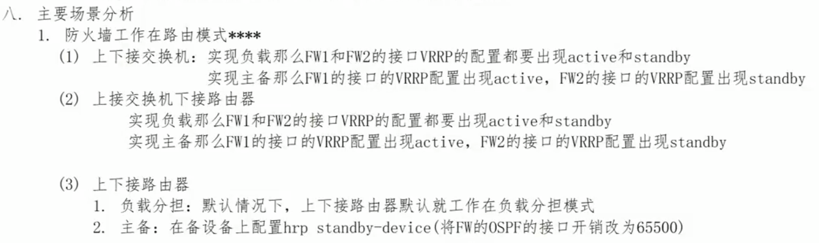
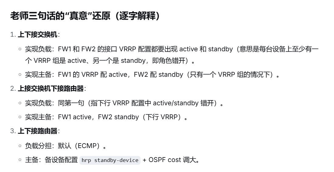
When Both Sides Connect to Switches, Use Full VRRP Redundancy
This is the easiest scenario to understand. Both the internal and external sides connect through Layer 2 switching networks, so the firewall must provide a virtual gateway IP and virtual MAC on both upstream and downstream interfaces. As a result, active/standby failover appears as if the same gateway is now being carried by a different physical device.
VGMP coordinates device-level active/standby status so that multiple VRRP groups switch consistently. HRP synchronizes session tables and server mappings to keep connections alive as much as possible after failover.
# FW1 example: enable VRRP on both upstream and downstream interfaces, and enable the HRP heartbeat
interface GigabitEthernet1/0/1.10
 vlan-type dot1q 10
 ip address 192.168.10.2 24
 vrrp vrid 10 virtual-ip 192.168.10.1  # Internal virtual gateway

interface GigabitEthernet1/0/2.100
 vlan-type dot1q 100
 ip address 200.1.1.2 24
 vrrp vrid 100 virtual-ip 200.1.1.1    # External virtual gateway

interface GigabitEthernet1/0/3
 ip address 172.16.0.1 24
 hrp enable                              # Enable active/standby heartbeat and state synchronization
This configuration defines the virtual gateways and heartbeat link that form the minimum framework for a dual-switch topology.
When the Downstream Side Uses a Switch and the Upstream Side Uses a Router, You Must Split the Mechanisms
This is the topology most likely to be misconfigured in production. The downstream side still faces a Layer 2 network, so it must continue using VRRP. However, when the upstream side connects directly to a Layer 3 router, the router does not make decisions based on a virtual MAC. It selects the better next hop according to its routing table.
For that reason, you should not mechanically extend VRRP to the upstream side. Instead, use OSPF, BFD-assisted static routes, or another dynamic routing mechanism so the router can detect whether the primary firewall is reachable.
# Upstream directly connected to a router: use BFD to track static route health
interface GigabitEthernet1/0/2
 ip address 100.1.1.2 30

bfd
ip-link 1 destination 100.1.1.1 interface GigabitEthernet1/0/2
ip route-static 0.0.0.0 0.0.0.0 100.1.1.1 track ip-link 1  # Withdraw the default route if the upstream link fails
hrp track ip-link 1                                          # Trigger active/standby switchover when detection fails
This configuration uses BFD to quickly detect upstream reachability loss and passes the link state to the active/standby switchover logic.
In Layer 3 Upstream Scenarios, OSPF Is Usually the Better Control Plane Choice
If the network can run dynamic routing, OSPF is usually more scalable than static routing plus BFD. The primary firewall advertises a lower cost, while the standby firewall increases its cost through hrp ospf-cost increase, allowing it to stay online without becoming the preferred path.
# OSPF approach: low cost on the primary firewall, high cost on the standby firewall
ospf 1
 area 0
  network 100.1.1.0 0.0.0.3
 default-route-advertise cost 10   # The primary firewall advertises a low-cost default route

# The standby firewall is often configured with the following strategy
# hrp ospf-cost increase 65500      # Automatically raise the route cost on the standby firewall
This configuration ensures that the router always prefers the primary firewall and automatically switches to the standby firewall after a failure.
When Both Sides Connect to Routers, Use a Pure Layer 3 Dynamic Routing Design
In a full Layer 3 scenario, the firewall usually no longer acts as the default gateway for endpoints, so VRRP is no longer necessary. Internal and external routers form adjacencies with both the primary and standby firewalls, and the routing protocol determines which device carries the primary path.
In this design, VGMP still controls device-level active/standby roles, and HRP still synchronizes sessions, but traffic switchover is driven primarily by OSPF or BGP convergence rather than virtual IP migration.
# Full Layer 3 scenario: run OSPF on both upstream and downstream interfaces
interface GigabitEthernet1/0/1
 ip address 192.168.1.2 30

interface GigabitEthernet1/0/2
 ip address 200.1.1.2 30

ospf 1
 area 0
  network 192.168.1.0 0.0.0.3
  network 200.1.1.0 0.0.0.3
 default-route-advertise always cost 10  # Prefer the default route from the primary firewall

# The standby firewall typically also includes:
# hrp ospf-cost increase 65500            # Increase the path cost on the standby firewall
This configuration keeps both devices online while ensuring that only the primary firewall path is preferred, which supports high availability and simpler future expansion.
Active/Standby Mode and Load Sharing Mode Must Be Understood Separately
Many engineers confuse VGMP-controlled active/standby behavior with manual role reversal inside individual VRRP groups. By default, VGMP centrally controls all VRRP group states on the local device. If the device is Active, most VRRP groups become Master. If the device is Standby, most VRRP groups become Backup.
If you want different VLANs to use different firewalls, you must explicitly configure active or standby in specific VRRP groups. That breaks VGMP’s default unified behavior and enables load sharing.
Load Sharing Does Not Replace Active/Standby; It Refines VRRP Ownership
| Mode | Number of VRRP Groups | Traffic Pattern | Configuration Characteristic |
|---|---|---|---|
| Active/Standby Mode | Usually one group or multiple unified groups | One primary device forwards traffic | You may not need to explicitly configure active/standby |
| Load Sharing Mode | At least two groups | Two devices carry different services | Requires staggered active/standby configuration |
 AI Visual Insight: This diagram illustrates the active/standby relationship in a dual-device hot standby deployment and the interface ownership on each firewall. It typically labels FW1, FW2, the heartbeat link, and upstream/downstream traffic directions to show which side depends on VRRP, which side depends on dynamic routing, and how traffic reconverges to the new active device after failover.
 AI Visual Insight: This diagram more likely emphasizes the configuration differences between active/standby mode and load sharing mode. The focus is on the staggered master/backup relationship of multiple VRRP groups across two firewalls, and on how manual
 active/standby assignments override VGMP’s centralized control logic.
The Conclusion Is to Identify Interface Types First, Then Choose the Redundancy Protocol Stack
When evaluating a firewall dual-device hot standby design, do not start by memorizing commands. Start by asking two questions instead: is the downstream neighbor a switch or a router, and is the upstream neighbor a switch or a router? Different answers lead to completely different protocol stacks.
A simple way to remember the design is this: Layer 2 neighbors rely on VRRP to abstract gateway ownership, Layer 3 neighbors rely on dynamic routing to control the best path, VGMP manages device-wide state, and HRP preserves session continuity.
FAQ
1. Why is VRRP usually not recommended on the upstream side when it connects to a router?
Because routers make forwarding decisions based on routing tables and next hops, not on switch-style MAC learning. In this scenario, the better design is to let the router detect active/standby state through OSPF, BFD, or static route tracking.
2. What problem does each of VGMP, VRRP, and HRP solve?
VRRP provides a virtual gateway and enables transparent failover for Layer 2 neighbors. VGMP centrally manages device-wide active/standby state to prevent inconsistent status across multiple VRRP groups. HRP synchronizes configuration, sessions, and mapping tables to reduce the impact of failover on live traffic.
3. Why must you explicitly configure active/standby in load sharing mode?
Because by default, VGMP aligns local VRRP groups with the device role. To make different VLANs use different firewalls, you must manually break that unified control model and create a staggered master/backup distribution across VRRP groups.
AI Readability Summary
This article systematically breaks down three typical firewall dual-device hot standby topologies in routing mode. It explains why switch-facing and router-facing deployments use different combinations of VRRP, dynamic routing, BFD, VGMP, and HRP, and it outlines practical configuration ideas for both active/standby and load sharing designs.