Flink Shuffle is the critical data exchange path in distributed execution. Its core capability is to let upstream tasks send data to downstream InputGates through ResultPartition, BufferPool, and Netty, while using a Credit-Based mechanism to prevent buffer buildup and uncontrolled backpressure. Keywords: Flink Shuffle, ResultPartition, InputGate
Technical specification snapshot
| Parameter | Description |
|---|---|
| Core topic | Flink Shuffle data exchange mechanism |
| Key components | ResultPartition, InputGate, NetworkBufferPool, Netty |
| Primary language | Java |
| Communication protocol | Netty-based TCP network transport |
| Default flow control | Credit-Based Flow Control |
| Typical modes | Pipelined Shuffle, Blocking Shuffle |
| Star count | Not provided in the original input |
| Core dependencies | Apache Flink Runtime, Netty, MemorySegment/BufferPool |
Flink Shuffle forms the core data plane between upstream and downstream tasks
Shuffle does not merely answer the question, “Can data be transferred?” It answers a harder question: “How can data be transferred reliably across parallel tasks, slots, and nodes?” In Flink, operator chaining only covers execution within a single task. Once data must flow to other parallel subtasks, it has to enter the Shuffle path.
Its value appears in four areas: it decouples upstream and downstream execution, supports parallel scale-out, establishes the path for backpressure propagation, and provides the foundation for fault tolerance and resource control. If you want to identify the real causes of throughput drops, network congestion, or rising latency, you need to understand this path end to end.
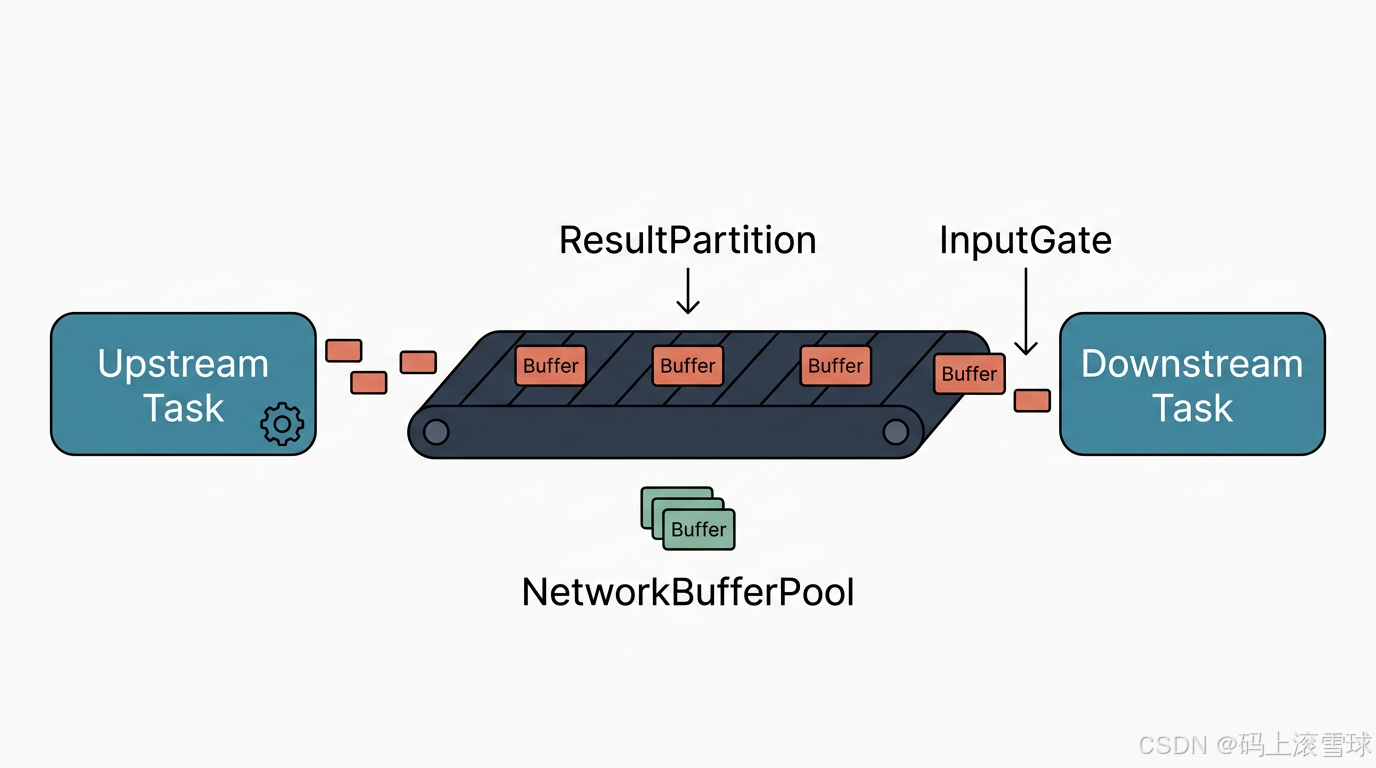 AI Visual Insight: This diagram shows the overall structure Flink uses to decouple task execution from network transport. Upstream operators do not write directly into downstream operators. Instead, they first enter the Shuffle path. The diagram highlights that cross-task data exchange defines the boundary of distributed execution and the starting point of backpressure propagation.
The three-layer Flink Shuffle architecture completes data exchange together
Flink Shuffle can be abstracted into three layers: the logical layer, the resource layer, and the communication layer. The logical layer defines producer and consumer interfaces, the resource layer handles buffering and memory allocation, and the communication layer performs actual cross-node transmission.
| Layer | Components | Responsibility |
|---|---|---|
| Logical layer | ResultPartition, InputGate | Abstract data production and consumption |
| Resource layer | NetworkEnvironment, NetworkBufferPool | Manage network buffers and memory segments |
| Communication layer | NettyServer, NettyClient | Handle remote data transport |
// Simplified path for upstream output entering Shuffle
RecordWriter.emit(record);                 // Write the record to the writer
resultPartition.emitRecord(buffer, 0);    // Write to the target partition
bufferPool.requestBufferBuilder();         // Request a writable buffer
nettyClient.writeAndFlush(message);        // Send to the downstream task over the network
This code summarizes the shortest path from operator output to the network sending channel.
ResultPartition handles upstream outbound data and partitioning
ResultPartition is the output container for an upstream task. It is not a simple queue. It acts as a partition manager: it routes records into different ResultSubpartitions and, once a buffer is full, turns it into a consumable BufferConsumer.
Each downstream parallel subtask usually corresponds to one subpartition. This allows the upstream side to control data routing precisely. Distribution strategies such as forward, rebalance, and hash-based routing after keyBy all ultimately map to partitioned writes.
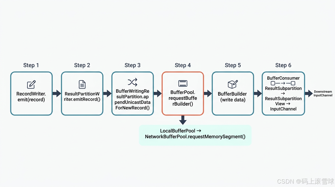 AI Visual Insight: This diagram focuses on how records enter ResultPartition from RecordWriter, are split, and are written into multiple subpartitions. Once a buffer is full, it becomes a consumable unit. This shows that Flink does not push records over the network one by one. It sends data in buffer-sized batches to improve throughput.
The upstream write path reflects a buffer-first design
// ResultPartition write path example
RecordWriter.emit(record);                                     // The upstream operator produces a record
partitionWriter.emitRecord(serializedBuffer, channelIndex);    // Write to the target channel
bufferWritingPartition.appendUnicastDataForNewRecord(buf, i);  // Append to the partition buffer
bufferPool.requestBufferBuilder(i);                            // Request a new buffer builder
networkBufferPool.requestMemorySegment();                      // Request a memory segment from the global pool
This path shows that Flink first requests memory segments and writes data in batches before exposing it to downstream consumers.
Two design points matter here. First, the buffer, not the individual record, is the fundamental unit of network transport. Second, NetworkBufferPool is a shared resource pool. All network exchanges compete for it, which makes it a major source of both performance bottlenecks and backpressure signals.
InputGate completes downstream consumption and pacing through active pulling
Unlike a pure upstream push model, Flink’s downstream side behaves more like an active consumer. InputGate aggregates multiple InputChannels, polls data from different upstream partitions in a unified way, and then passes the data to operators for continued processing.
The key value of InputGate is not only that it receives data, but that it establishes a demand-driven consumption boundary. When the downstream side cannot keep up, it does not receive data without limits. Instead, it uses credits to constrain the upstream sending rate and prevent buffer exhaustion.
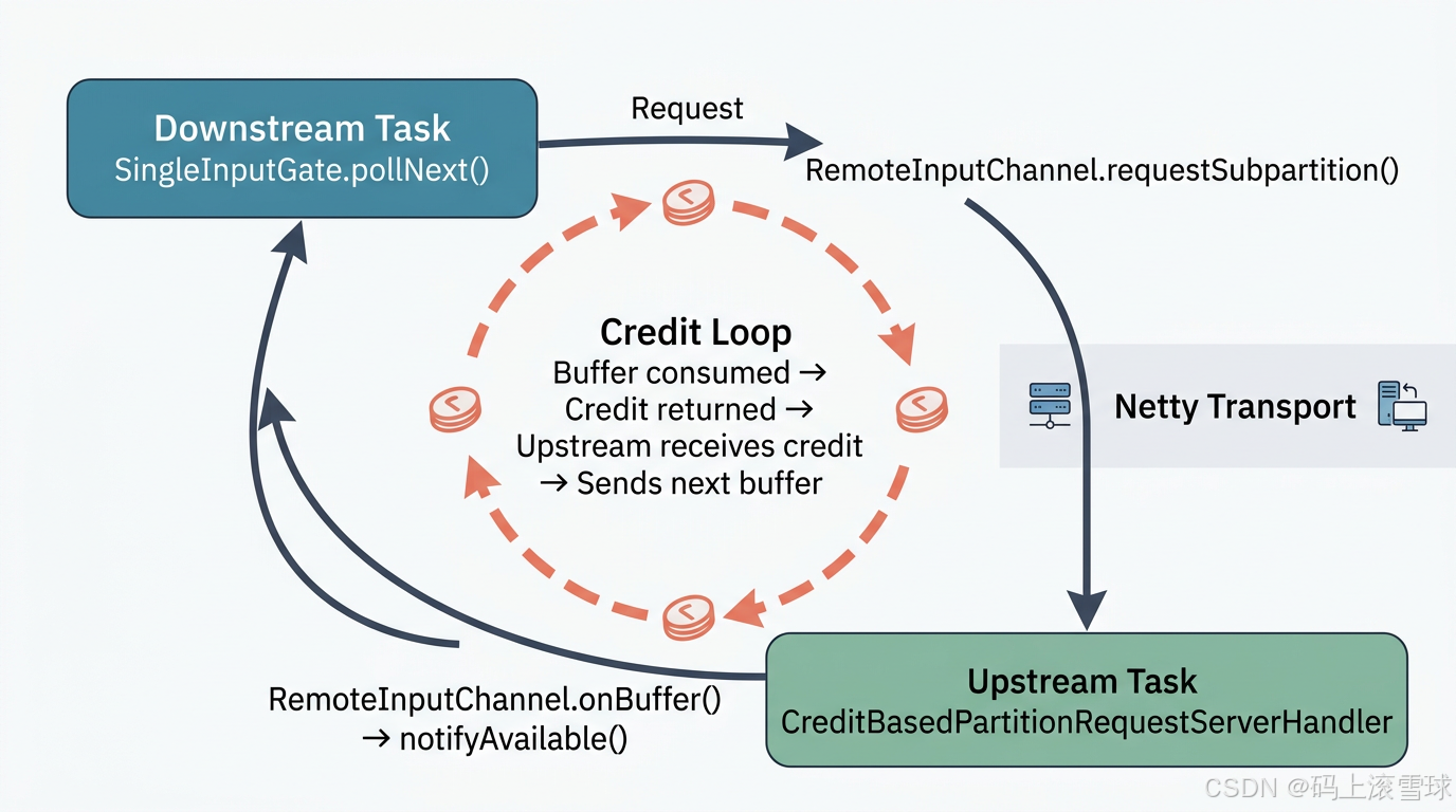 AI Visual Insight: This diagram shows the collaboration between the downstream InputGate and remote InputChannels, with special emphasis on credits as send permissions. Only when the downstream side holds enough buffer resources can the upstream side continue sending buffers. This directly forms the low-level implementation of Flink backpressure control.
Credit-Based mode is the core of Flink’s default flow control
// Key process for downstream data fetching
BufferOrEvent next = singleInputGate.pollNext();   // Poll the next data block or event
remoteChannel.requestSubpartition(subpartition);   // Request data from the remote subpartition
clientHandler.processBufferResponse(response);     // Process the received buffer response
remoteChannel.onBuffer(buffer, sequenceNumber);    // Put the buffer into the local receive queue
remoteChannel.notifyAvailable();                   // Notify the upper layer that data is available for consumption
This code describes how the downstream side initiates requests, receives buffers, and exposes them to the task for consumption.
The Credit-Based mechanism can be summarized like this: the downstream side grants as many send permissions as the number of available buffers it currently holds; after consuming one buffer, it returns one credit. This both limits the sending rate and feeds consumer-side slowness back to the upstream side with precision.
Different Shuffle modes define the trade-offs among latency, throughput, and resource usage
Flink does not provide only one Shuffle implementation. Different job types, execution semantics, and resource goals lead to different choices. Batch jobs tend to use Blocking Shuffle, while streaming jobs use Pipelined Shuffle by default, combined with Credit-Based flow control for low-latency transport.
| Mode | Characteristics | Typical use case |
|---|---|---|
| Blocking Shuffle | Upstream writes everything first, downstream reads afterward | Batch processing |
| Pipelined Shuffle | Upstream and downstream run concurrently | Stream processing |
| Credit-Based Shuffle | Uses credits to regulate sending speed | Default streaming network transport |
| Remote Shuffle Service | Separates storage from compute | Cloud-native and elastic architectures |
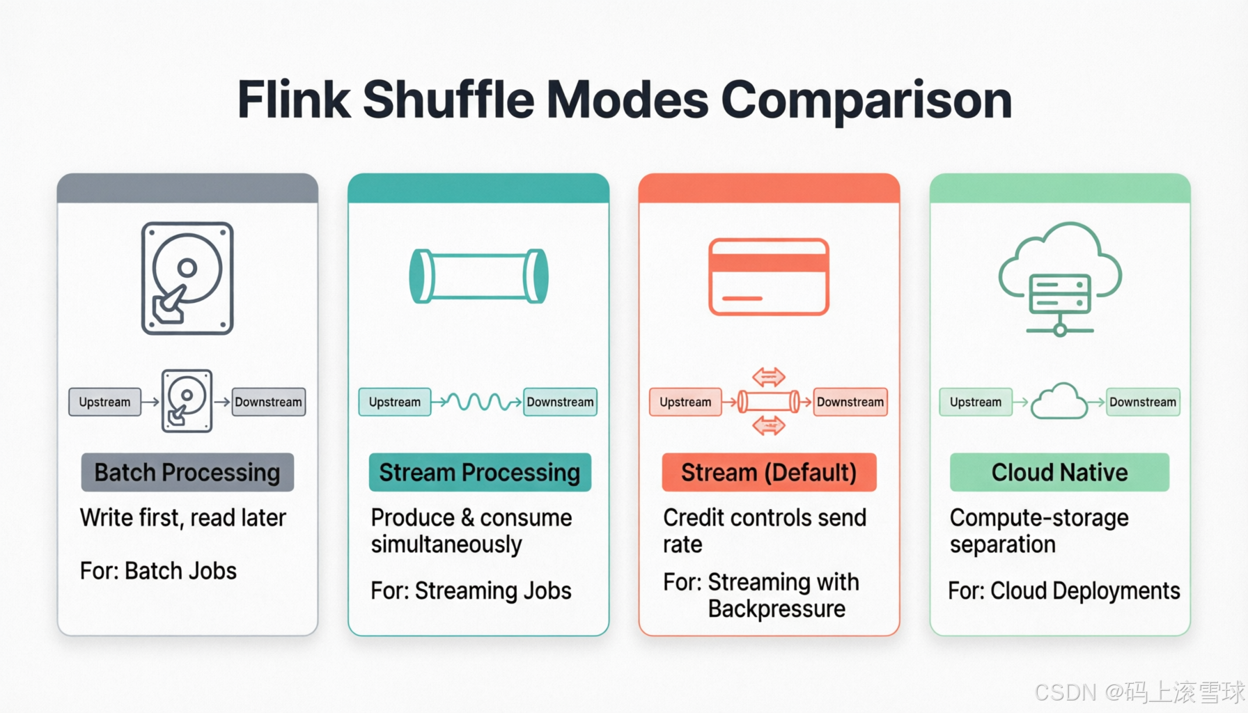 AI Visual Insight: This diagram compares several Shuffle variants. The key differences are whether data is consumed while it is being produced and whether flow control is driven by downstream credits. It helps explain why stream processing depends more heavily on the combination of Pipelined and Credit-Based Shuffle to reduce end-to-end latency.
The main source code path connects task execution and network transport
// Key call chain from operator processing to downstream reception
StreamTask.processInput();                         // Process input data
recordWriter.emit(record);                         // Emit a record
resultPartitionWriter.emitRecord(buf, channel);    // Write to the result partition
resultSubpartition.add(bufferConsumer);            // Add to the subpartition queue
singleInputGate.pollNext();                        // Downstream polls for data
remoteInputChannel.onBuffer(buffer, seq);          // Receive the remote buffer
This main path reveals the essence of Flink Shuffle: a continuous process of operator output → partition buffering → network transport → downstream polling.
Understanding Shuffle is essential for diagnosing real Flink performance issues
If throughput drops, first check whether buffers are under pressure. If latency rises, inspect whether downstream credits remain insufficient for long periods. If network fluctuations become obvious, focus on Netty channels and the buildup of remote partition requests. Most backpressure in Flink jobs can ultimately be traced back to resource imbalance along this path.
From an architectural point of view, ResultPartition handles outbound data, InputGate handles inbound consumption, NetworkBufferPool controls capacity, and Netty performs cross-node transport. Together, they form the most important data plane in the Flink runtime.
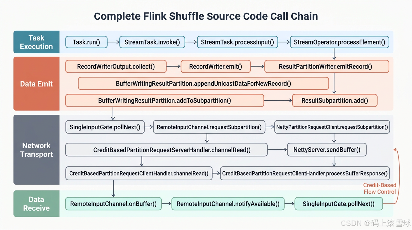 AI Visual Insight: This diagram combines task execution, buffer management, network transport, and downstream reception into one complete path, highlighting the call relationships among runtime components. Views like this are especially useful when reading source code because they clarify which layer to inspect first during performance analysis.
FAQ
1. Why does Flink need Credit-Based Flow Control?
Because a pure push model can quickly fill downstream buffers. Credit-Based Flow Control lets the downstream side constrain the upstream sending rate using the number of available buffers. It is the foundation for backpressure handling, stability, and low memory amplification.
2. What roles do ResultPartition and InputGate play?
ResultPartition is the producer-side output manager. It handles partitioning, buffering, and outbound delivery. InputGate is the consumer-side entry point. It pulls data from multiple InputChannels and delivers it to downstream operators in consumable order.
3. Why is Pipelined Shuffle more common in stream processing?
Because it allows the upstream side to produce while the downstream side consumes, without waiting for an entire batch to be written to disk first. This significantly reduces end-to-end latency and better matches the continuous processing requirements of real-time computing.
Core summary
This article reconstructs the core Flink Shuffle path, focusing on how ResultPartition, InputGate, NetworkBufferPool, and Netty work together. It explains how data moves across tasks and nodes, and how Credit-Based Flow Control supports backpressure management, throughput, and low-latency execution.