[AI Readability Summary]
This lab walks through a complete MGRE multipoint tunnel design for enterprise branch interconnection. It combines underlay reachability, link encapsulation, authentication, GRE, MGRE, NHRP, static default routing, and RIP v2 to connect headquarters and multiple branch sites. The key idea is to validate the underlay first, then build the overlay tunnel network for private route exchange.
Technical specifications are summarized below
| Parameter | Description |
|---|---|
| Lab topic | Comprehensive MGRE multipoint tunnel networking lab |
| Device style | Common Huawei VRP / eNSP command model |
| Core protocols | PPP, HDLC, GRE, MGRE, NHRP, RIP v2 |
| Topology model | Hub-and-Spoke, headquarters plus multiple branches |
| Routing method | Static default routes plus RIP dynamic routing |
| Core dependencies | Tunnel interfaces, Serial interfaces, NHRP registration, RIP advertisement |
| Star count | No valid repository data provided in the original source |
| Use cases | Enterprise branch interconnection, lab instruction, tunnel technology validation |
This lab demonstrates the full evolution path of enterprise WAN interconnection
The original lab does more than explain MGRE. It connects lower-layer link encapsulation, authentication, basic reachability, and dynamic routing into one end-to-end workflow. It starts with IP address planning, then establishes public network reachability, and finally uses MGRE to carry private route exchange.
This design is very close to real-world engineering practice: validate the underlay first, then build the overlay tunnel. Understanding this matters more than memorizing commands.
 AI Visual Insight: This diagram shows a multi-router lab topology with nodes such as R1, R2, R3, R4, and R5, along with several PC subnets. The central node acts as a public transit device, while different branches connect through serial links or tunnels. The topology is well suited for validating Hub-and-Spoke tunnels, static default routing, and private dynamic routing working together.
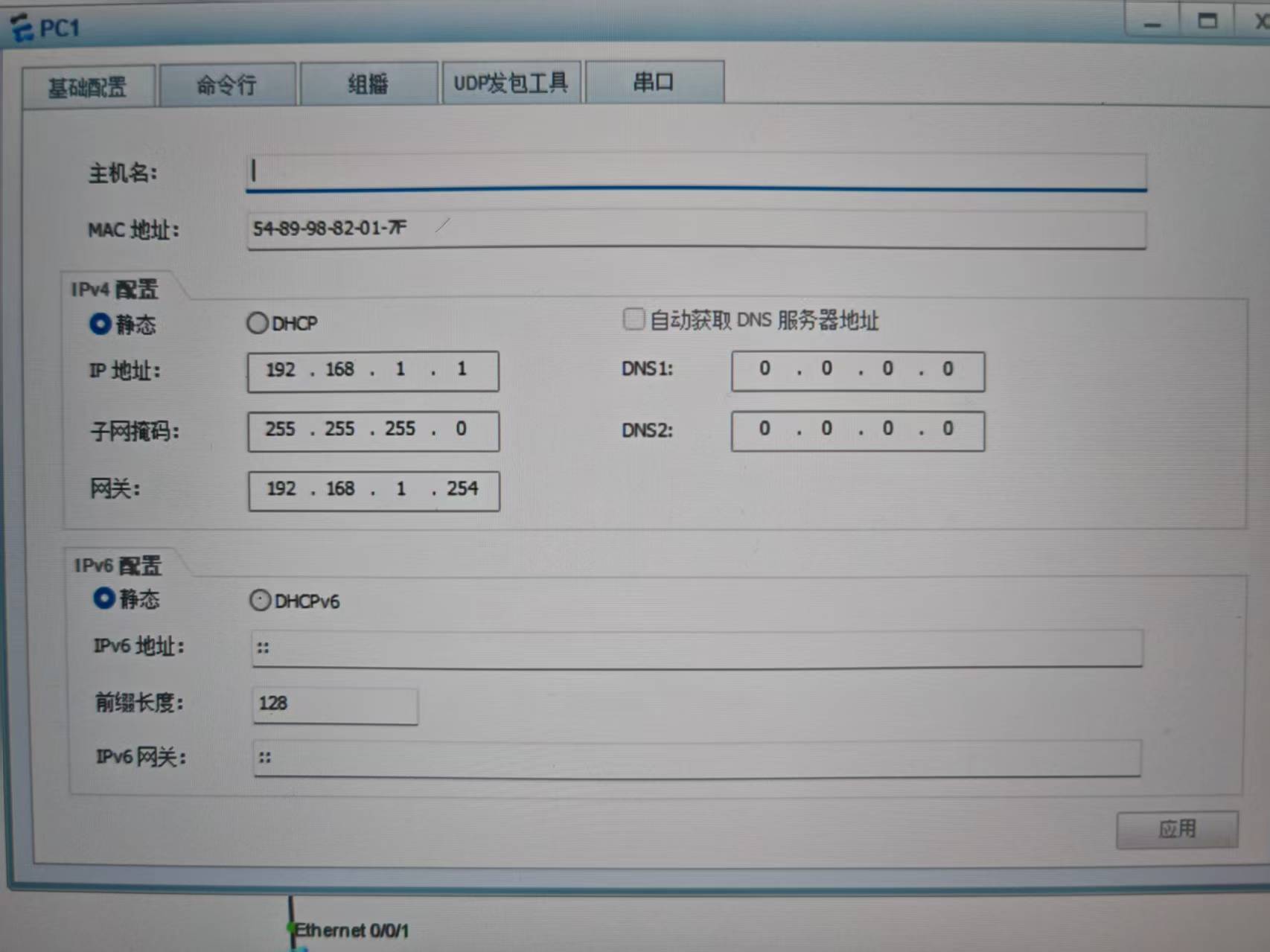
Address planning is the prerequisite for later route convergence
The four endpoint subnets in the article are 192.168.1.0, 192.168.2.0, 192.168.3.0, and 192.168.4.0. The tunnel subnets use 10.1.1.0/24 and 10.1.2.0/24 for point-to-point GRE and MGRE, respectively.
It is best to manage public interconnection addresses and private service addresses in separate layers. Otherwise, troubleshooting becomes much harder because you cannot easily tell whether the issue is in the physical link, the tunnel, or route advertisement.
# Endpoint subnet examples
PC1 192.168.1.1
PC2 192.168.4.1
PC3 192.168.2.1
PC4 192.168.3.1

# Planning principle: separate service subnets from tunnel subnets  # Helps isolate the fault domain
# Service subnets: 192.168.x.0/24                                 # Carries endpoint communication
# Tunnel subnets: 10.1.x.0/24                                     # Carries GRE/MGRE adjacency
The configuration above shows the lab’s basic address segmentation model.
Static default routing provides public reachability for tunnel establishment
R1, R2, R3, and R4 all point their default routes to R5. The logic is straightforward: send all unknown traffic to the transit node first, then let it forward the traffic further. This is one of the most common prerequisite steps before building GRE or MGRE.
# Default routes from each branch toward the central public node
R1: ip route-static 0.0.0.0 0 15.1.1.5   # R1 sends default traffic to R5
R2: ip route-static 0.0.0.0 0 25.1.1.5   # R2 sends default traffic to R5
R3: ip route-static 0.0.0.0 0 35.1.1.5   # R3 sends default traffic to R5
R4: ip route-static 0.0.0.0 0 45.1.1.5   # R4 sends default traffic to R5
This step establishes baseline Layer 3 reachability for the underlay.
Link encapsulation and authentication validate multiple WAN access methods
The lab intentionally mixes PAP, CHAP, and HDLC to simulate heterogeneous branch access methods. That makes it useful for modeling real networks where different branches may use different link technologies.
R1 and R5 use PPP PAP, with R5 acting as the authenticator. R2 and R5 use PPP CHAP. R3 and R5 use HDLC. This proves that the upper-layer MGRE tunnel does not depend on a single Layer 2 encapsulation type.
# R5 acts as the PAP authenticator
aaa
 local user wangdaye password cipher wdy12345   # Create a local authentication user
 local user wangdaye privilege level 15
 local user wangdaye service-type ppp           # Allow PPP to use this account for authentication
quit
interface Serial4/0/1
 ppp authentication-mode pap                    # Enable PAP authentication

# R1 acts as the authenticated peer
interface Serial4/0/0
 ppp pap local-user wangdaye password cipher wdy12345   # Submit PAP credentials
This configuration establishes the PAP-authenticated link.
# R2 and R5 use CHAP
# R5
interface Serial3/0/1
 ppp authentication-mode chap                   # Enable CHAP authentication

# R2
interface Serial4/0/0
 link-protocol ppp                              # Switch serial encapsulation to PPP
 ppp chap user wangdaye                         # Define the CHAP username
 ppp chap password cipher wdy12345             # Configure the CHAP password

# R3 and R5 use HDLC
# R5 / R3
interface Serial4/0/0
 link-protocol hdlc                             # Use HDLC as the link-layer encapsulation
This configuration shows how multiple access links can transparently carry the upper-layer tunnel.
Building a point-to-point GRE tunnel first helps explain the minimum tunnel workflow
Before introducing MGRE, the article first builds a standard GRE tunnel between R1 and R4. This step is highly valuable because it proves that GRE encapsulation, source addressing, and destination addressing all work as expected.
# Point-to-point GRE between R1 and R4
# R1
interface Tunnel0/0/0
 ip address 10.1.1.1 255.255.255.0              # Configure the tunnel address
 tunnel-protocol gre
 source 15.1.1.1                                # Specify the tunnel source public address
 destination 45.1.1.4                           # Specify the peer public address

# R4
interface Tunnel0/0/0
 ip address 10.1.1.4 255.255.255.0
 tunnel-protocol gre
 source 45.1.1.4
 destination 15.1.1.1
This configuration validates the basic encapsulation model of point-to-point GRE.
MGRE and NHRP solve the scalability problem of multi-branch tunnels together
With standard GRE, adding each new branch may require a new tunnel. The key value of MGRE is that the Hub maintains only one multipoint Tunnel interface, while each Spoke uses NHRP to register the mapping between its tunnel address and public address with the central node.
In this lab, R1 is the Hub, and R2 and R3 are Spokes. They share the same NHRP network-id 100, and each branch submits its mapping through register.
# Hub: R1
interface Tunnel0/0/1
 ip address 10.1.2.1 255.255.255.0              # Hub tunnel address
 tunnel-protocol gre p2mp                       # Enable multipoint GRE
 source 15.1.1.1                                # Use a fixed public address as the source
 nhrp network-id 100                            # Define the NHRP logical domain
 nhrp entry multicast dynamic                   # Allow dynamic pseudo-broadcast

# Spoke: R2
interface Tunnel0/0/1
 ip address 10.1.2.2 255.255.255.0
 tunnel-protocol gre p2mp
 source Serial4/0/0                             # Use the local outbound interface as the source
 nhrp network-id 100
 nhrp entry 10.1.2.1 15.1.1.1 register          # Register the tunnel/public mapping with the Hub

# Spoke: R3
interface Tunnel0/0/1
 ip address 10.1.2.3 255.255.255.0
 tunnel-protocol gre p2mp
 source Serial4/0/0
 nhrp network-id 100
 nhrp entry 10.1.2.1 15.1.1.1 register          # Register with the same Hub
This configuration builds the MGRE overlay and enables NHRP neighbor discovery.
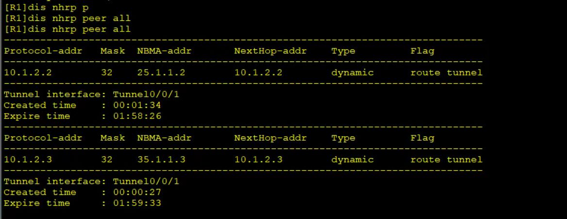 AI Visual Insight: This image most likely shows Tunnel interface or NHRP neighbor status. The key point is that the Hub has learned registration entries from multiple Spokes. That means the central node can dynamically resolve branch tunnel addresses to public NBMA addresses, which is the core indicator of a working multipoint GRE deployment.
RIP v2 injects private subnets into the virtual WAN
A working tunnel does not automatically mean business traffic works. Dynamic route propagation is what actually enables communication between PC subnets. The article uses RIP v2 because it is simple to configure and well suited for teaching route learning and advertisement.
The Hub and branches also disable RIP split horizon. Otherwise, routes learned through the same Tunnel interface would not be re-advertised, and Spoke-to-Spoke communication would fail.
# RIP v2 advertises service and tunnel subnets
R1:
rip 1
 undo summary                                   # Disable automatic summarization
 version 2
 network 192.168.1.0                            # Advertise the headquarters service subnet
 network 10.0.0.0                               # Advertise tunnel-related subnets

R2:
rip 1
 undo summary
 version 2
 network 192.168.2.0
 network 10.0.0.0

R3:
rip 1
 undo summary
 version 2
 network 192.168.3.0
 network 10.0.0.0

R4:
rip 1
 undo summary
 version 2
 network 192.168.4.0
 network 10.0.0.0

# Disable split horizon
interface Tunnel0/0/1
 undo rip split-horizon                         # Allow RIP routes learned on the interface to be advertised back out
This part enables private route exchange between headquarters and branches, as well as between branches.
Connectivity testing is the final standard for proving the lab is complete
After NHRP registration succeeds and RIP converges, validate four outcomes: the Tunnel interfaces are up, NHRP neighbors exist, the routing table contains remote private subnets, and end hosts can ping each other successfully. The article’s final full-network test is a consolidated acceptance check for these goals.
If branch-to-branch communication fails, check these three items first: whether the Hub has enabled nhrp entry multicast dynamic, whether RIP split horizon is disabled on the Tunnel, and whether the Spokes correctly registered their public mappings with the Hub.
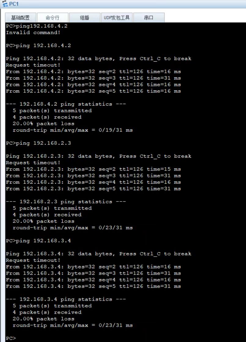 AI Visual Insight: This image is likely a ping or route verification result. If it shows continuous successful replies, it confirms that the underlay, MGRE tunnel, NHRP mapping, and RIP route propagation have formed a complete end-to-end workflow. It directly proves that the private service network now supports end-to-end communication.
FAQ
1. Why must MGRE be used together with NHRP?
MGRE solves only the encapsulation problem of a one-to-many tunnel interface. It does not solve automatic discovery of remote public addresses. NHRP provides dynamic mappings from tunnel addresses to NBMA public addresses, which makes it essential for automatic multi-branch tunnel establishment.
2. Why do you need to disable RIP split horizon for branch-to-branch connectivity?
The Hub receives RIP routes from multiple branches through the same Tunnel interface. If split horizon remains enabled, the Hub will not advertise routes learned from one branch back to other branches. As a result, Spokes cannot reach each other.
3. Why does this lab configure PPP/HDLC before MGRE?
PPP PAP, PPP CHAP, and HDLC simulate different WAN access methods and validate underlay reachability. MGRE is an overlay technology and depends on a stable underlying public network path. Building the lower layer first and then the tunnel is the sequence that best matches engineering practice.
Core summary: This article reconstructs a typical end-to-end MGRE lab that covers address planning, static routing, PPP PAP/CHAP, HDLC, GRE, MGRE, NHRP, and RIP v2. It helps you quickly understand private network connectivity between headquarters and branches, as well as branch-to-branch communication, in a Hub-and-Spoke design.