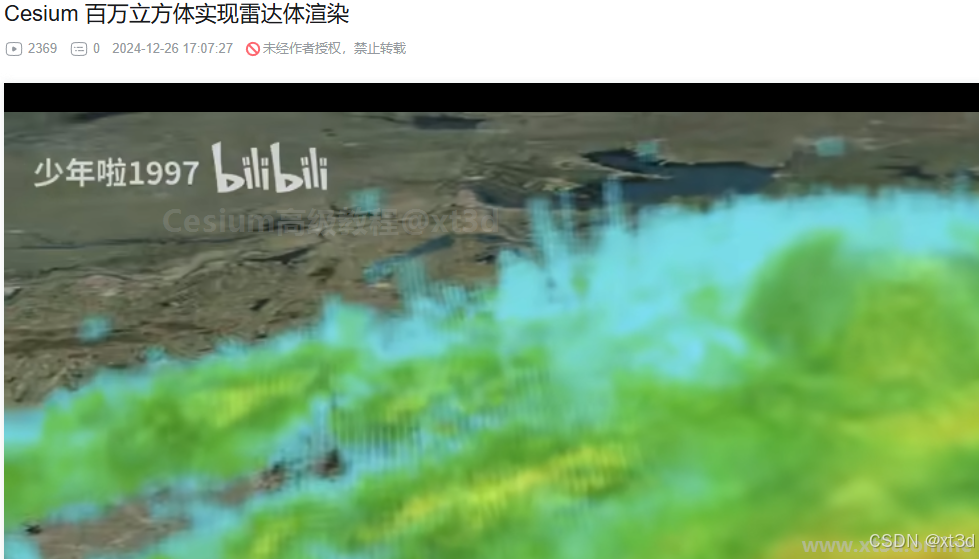
This article explains how to display million-scale voxel clouds in Cesium by combining BoxGeometry, 3D textures, and instanced rendering. The approach avoids the integration complexity of traditional volume rendering and reduces the performance pressure of massive geometry workloads. Core keywords: Cesium, volume rendering, instanced rendering.
The technical specification snapshot outlines the implementation
| Parameter | Description |
|---|---|
| Core languages | JavaScript, GLSL |
| Rendering framework | Cesium |
| Graphic representation | BoxGeometry voxel instances |
| Data container | Texture3D |
| Low-level capabilities | DrawCommand, instanceCount |
| Data scale | Original voxels: 401×401×41, total 6,592,841 |
| Demo scale | 100×100×100, total 1,000,000 |
| Core dependencies | Cesium Viewer, WebGL2, sampler3D |
| Applicable scenarios | Weather clouds, volumetric data visualization, 3D GIS |
This approach approximates volume rendering with instanced geometry
The more common path for traditional volume rendering is ray marching. In production, however, many teams need an implementation that is more intuitive, easier to control, and simpler to integrate with Cesium. The idea here is to break volumetric data into a large number of voxels, then map each voxel to a BoxGeometry instance.
In essence, this is not strict high-fidelity volume rendering. Instead, it reconstructs the data distribution with discrete cubes. The main advantage is that it fits naturally into Cesium’s geometry system and combines more easily with picking, shadows, and alpha blending.
The mapping from voxels to geometry is straightforward
The original dataset size is 401×401×41, which theoretically requires 6,592,841 voxel instances. Even with instancing, that count still puts significant pressure on the GPU, memory, bandwidth, and fragment fill rate. For that reason, the example reduces the scale to 1 million instances so it can run on most machines.
 AI Visual Insight: The image shows the 3D cloud outline formed by aggregating discrete voxels. Its key characteristic is that a sense of volume emerges from stacking large numbers of regular cubes in space, which shows that this approach relies on geometric instance density rather than ray marching to represent volumetric structure.
A 3D texture stores the volumetric data instead of directly drawing primitives
The first step is not to draw boxes. The first step is to upload the volumetric dataset into a GPU-sampleable 3D texture. Then each instance can sample the corresponding voxel value from the texture during shading based on its spatial position.
fetch("/assets/volumeCloud.json")
  .then(res => res.json())
  .then(res => {
    const data = new Uint8Array(res.values); // Convert volume data into a GPU-ready byte array
    const texture = new Cesium.Texture3D({
      context: viewer.scene.context,
      source: { arrayBufferView: data }, // Upload voxel data into the 3D texture
      width: res.rows,
      height: res.cols,
      depth: res.heights,
      pixelFormat: Cesium.PixelFormat.RED
    });
  });
This code converts volumetric data from JSON into a 3D texture so later instance shaders can sample it by voxel coordinates.
Instanced rendering compresses Draw Calls into a manageable range
If you create BoxGeometry objects one by one, CPU submission cost quickly becomes unmanageable. This implementation uses DrawCommand with instanceCount so the GPU can repeatedly draw the same geometry data, while the vertex shader computes each box position from gl_InstanceID.
const command = new Cesium.DrawCommand({
  vertexArray: vertexArray,
  shaderProgram: shaderProgram,
  modelMatrix: modelMatrix,
  pass: Cesium.Pass.TRANSLUCENT,
  instanceCount: 100 * 100 * 100 // Submit 1 million instances in one draw
});
This code tells the GPU to reuse the same box vertex data and draw 1 million instances in sequence.
The instance index determines the spatial layout
Inside the vertex shader, the instance index is decomposed into X, Y, and Z coordinates. This eliminates the need to pass a separate position array for every instance while still constructing a regular 3D grid.
in vec3 position;
out vec4 v_color;

void main() {
  vec3 p = position.xyz * vec3(100.0, 100.0, 100.0); // Control the size of each voxel box
  int irow = 100;
  // gl_InstanceID is typically used here to compute ix, iy, and iz
  // ix, iy, and iz determine the current instance position in the 3D grid
  v_color = vec4(0.5, 0.5, 1.0, 0.6);
  gl_Position = czm_projection * czm_modelView * vec4(p, 1.0);
}
This code generates a regularly distributed cube array from the instance index and applies basic shading.
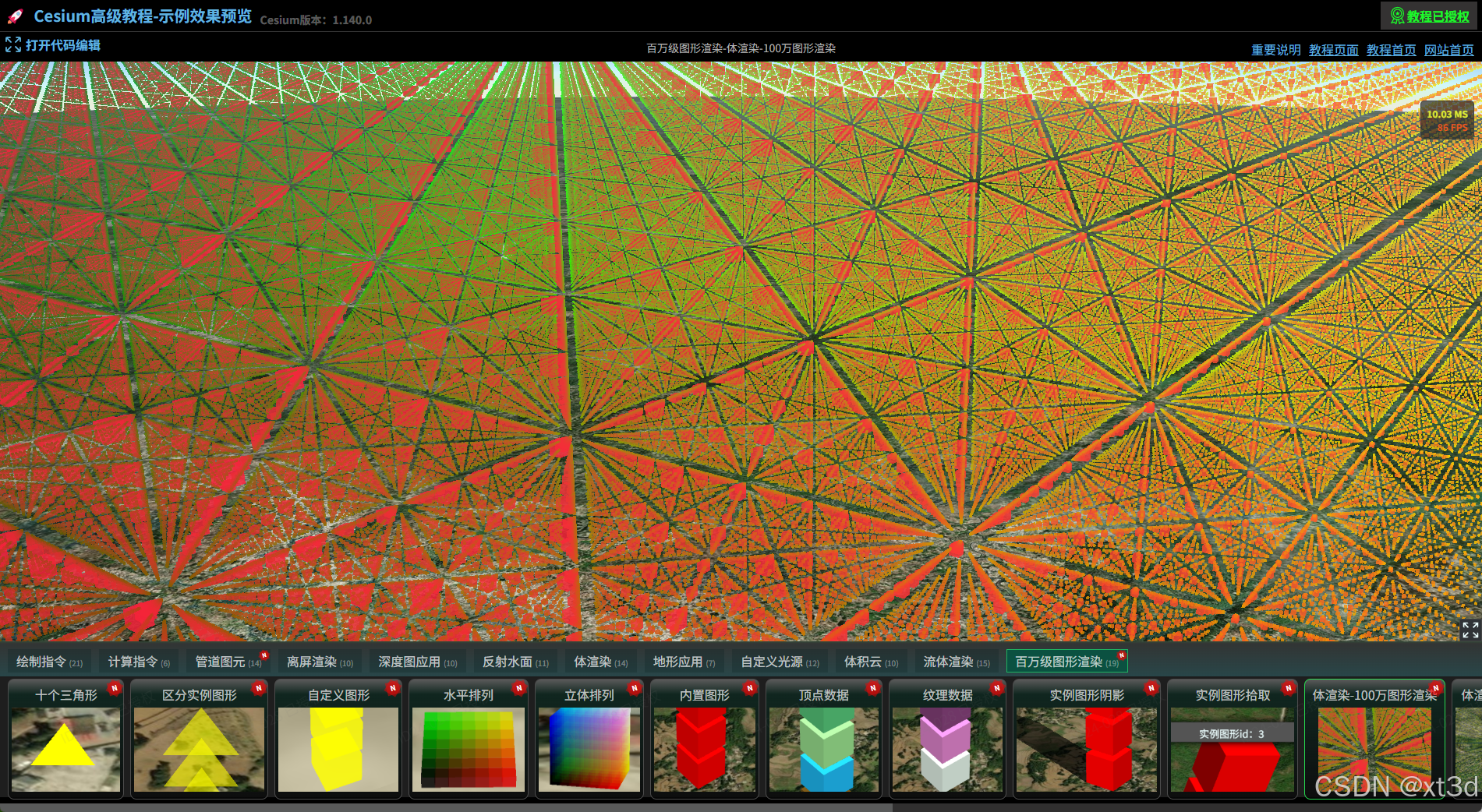 AI Visual Insight: The image shows instances evenly distributed in a regular 3D lattice. Color gradients follow spatial coordinates, which confirms that the mapping from gl_InstanceID to 3D indices is correct and that a single batched submission already forms a stable voxel-field skeleton.
Color mapping is driven by voxel values instead of fixed colors
Once instance positions map one-to-one to 3D texture coordinates, the shader can sample voxel values and map them to a color ramp by value range. This step determines the visual quality of clouds, temperature fields, or concentration fields.
let values = [0, 5, 10, 15, 20, 25, 30, 35, 40, 45, 50, 55, 60, 65];
let colors = [
  "rgb(0,0,0,0)",
  "rgb(170,36,250)",
  "rgba(212,142,254,0.13)",
  "rgba(238,2,48,0.12)",
  "rgba(254,100,92,0.11)"
];

colors = colors.map(item => Cesium.Color.fromCssColorString(item)); // Convert to Cesium color objects
This code defines a segmented mapping from voxel values to colors, which provides visual encoding for transparent cloud volumes or layered meteorological effects.
precision highp sampler3D;
in vec3 position;
out vec4 v_color;
uniform sampler3D map;

void main() {
  vec3 p = position.xyz * vec3(100.0, 100.0, 100.0);
  // Convert instance coordinates into texture coordinates
  // Sample the current voxel value from the 3D texture
  float value = 0.0; // Placeholder for the example; in practice this should be texture(map, uvw).r
  v_color = getColorByValue(value); // Map color by sampled value
  gl_Position = czm_projection * czm_modelView * vec4(p, 1.0);
}
This code binds each box color to the real voxel value, producing an approximate volume-rendering result.
Geometry size and spacing determine the final sense of volume
Once color mapping is connected, the scene may still look like sparse points. The cause is usually not a sampling issue. More often, the boxes are too small or the spacing is too large, so the volume lacks visual continuity.
The fix is straightforward: enlarge each voxel box or reduce the spacing between instances. In the example, changing the scale from 100 to 1000 noticeably improves the continuity of the cloud body.
void main() {
  vec3 p = position.xyz * vec3(1000.0, 1000.0, 1000.0); // Enlarge voxel boxes to strengthen the sense of volume
}
This code increases voxel geometry size so discrete instances look closer to a continuous volume.
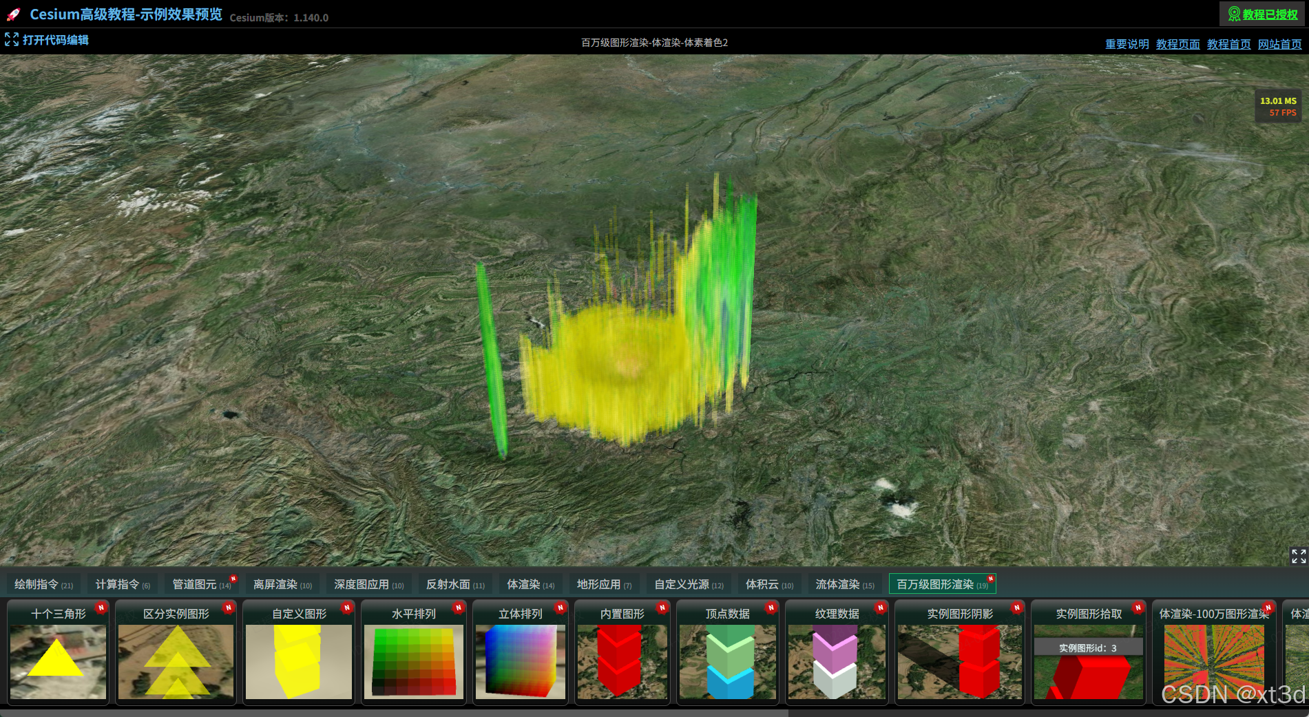 AI Visual Insight: The visual gaps between voxels are greatly reduced. The cloud begins to form continuous clustered structures, which shows that the box scale is now large enough to cover neighboring sample intervals. The sense of volume mainly comes from instance overlap and alpha blending.
Z-axis scale correction restores the true shape of the volumetric data
The original dataset is much smaller along the Z axis than along X and Y. If you scale all three dimensions equally, the final shape appears unnaturally stretched upward. You therefore need to compress the Z axis independently so the instance grid better matches the actual cloud thickness.
void main() {
  vec3 p = position.xyz * vec3(1000.0, 1000.0, 200.0); // Compress the Z-axis scale independently
}
This code corrects the depth ratio of the voxel grid so the visualized outline more closely matches the original volumetric structure.
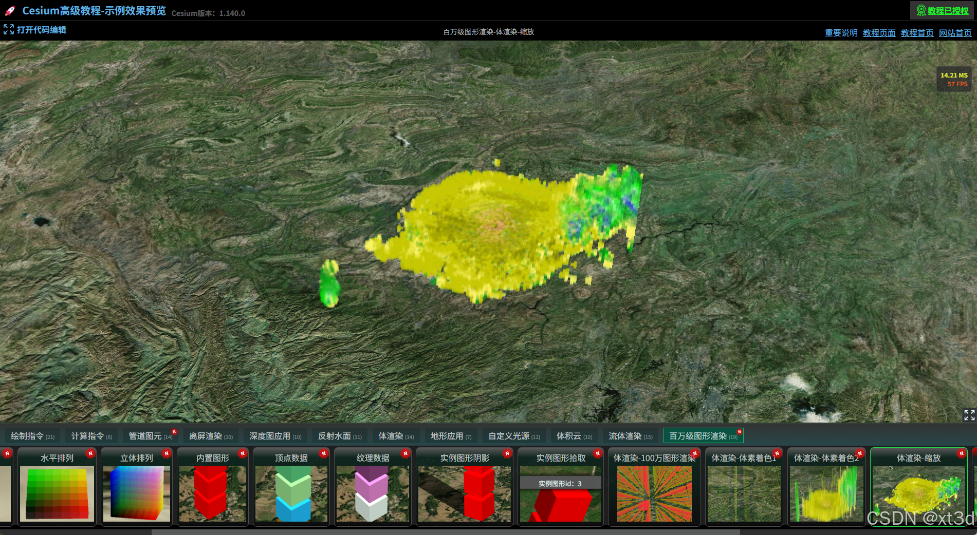 AI Visual Insight: The cloud thickness is visibly compressed, and the overall shape more closely matches a layered meteorological cloud distribution. This confirms that non-uniform scaling effectively restores the true vertical scale characteristics of the volumetric dataset.
The performance ceiling depends on instance scale and hardware capability
Instanced rendering significantly reduces Draw Calls, but it does not eliminate the cost of vertex processing, texture sampling, alpha blending, or fragment fill rate. In million-scale transparent box scenes, the bottleneck often shifts from CPU submission to GPU rendering.
Three optimization directions are more practical. First, resample by the real aspect ratio, for example changing 100×100×100 to 200×200×20. Second, cull low-value voxels to remove meaningless instances. Third, introduce LOD or chunked loading to avoid keeping the full dataset resident in GPU memory.
FAQ
Q1: Why not render all 6.59 million voxels directly?
A: It is theoretically possible, but 6.59 million transparent boxes create much higher vertex, fragment, and blending costs. One million instances is a practical compromise between visual quality and broad device compatibility.
Q2: How does this method differ from ray-marching volume rendering?
A: Ray marching is closer to true volume rendering and usually provides better continuity and finer detail. The instanced voxel approach is easier to implement in Cesium and works better for debugging, interaction, and engineering integration, but its visual fidelity is generally lower.
Q3: What should you optimize first?
A: Start with instance resolution and axis proportions. Rebalancing X, Y, and Z sampling density to match the true data shape usually improves both image quality and performance more effectively than blindly increasing instance count.
AI Readability Summary: This article reconstructs a practical Cesium workflow for million-instance volume visualization: use BoxGeometry to represent voxels, store volumetric data in a 3D texture, and rely on DrawCommand instancing to reduce Draw Calls. It also highlights the main performance bottlenecks and the geometry-scaling strategies that improve visual continuity.