This article focuses on high-efficiency digital electronics practice with SimulIDE. Its core approach is to use official examples and four robot-oriented circuit scenarios to quickly map logic gates, combinational logic, and sequential logic to safety interlocks, encoder decoding, counting, and fault display. It addresses the common gap between memorizing theory and applying it in real systems. Keywords: SimulIDE, digital electronics, robot engineering.
Technical Specifications at a Glance
| Parameter | Details |
|---|---|
| Primary Languages | C++ (core application), Arduino C++, Python (auxiliary analysis) |
| Simulation Targets | Digital circuits, mixed-signal circuits, Arduino interaction |
| Official Example Paths | examples/Digital, examples/Analog/Digital, examples/Micro/Arduino |
| Typical Protocols / Interfaces | UART, I2C, PWM, GPIO |
| Supported Platforms | Ubuntu, Linux, AppImage environments |
| Star Count | Not provided in the source material |
| Core Dependencies | 74LS logic ICs, 555 timer, Schmitt trigger, Arduino example environment |
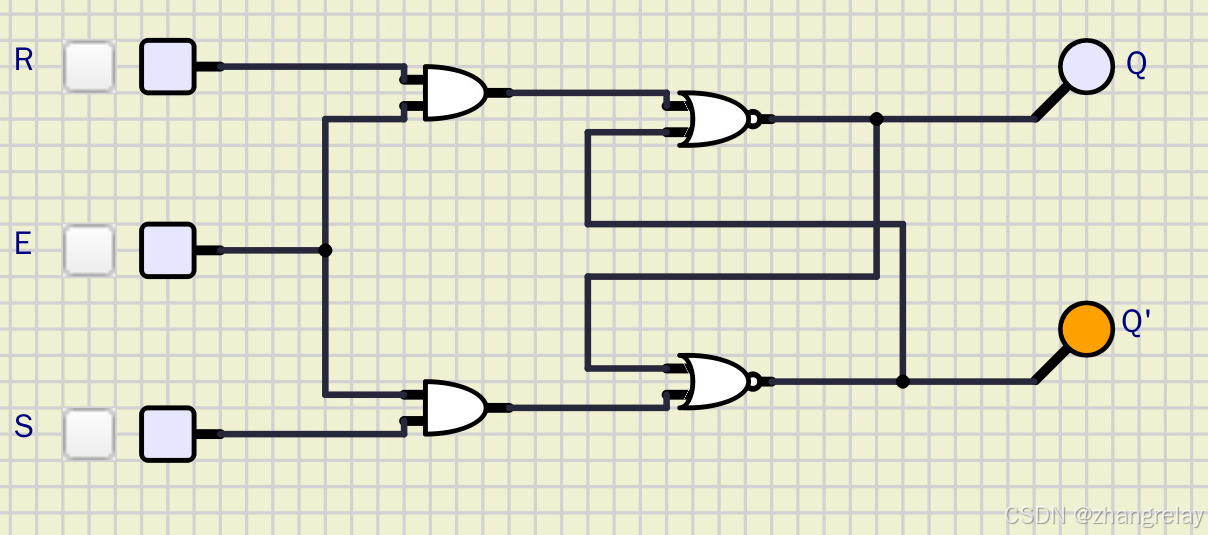 AI Visual Insight: This image shows a basic digital logic simulation canvas, typically including logic gates, input switches, and output indicators. It is used to verify truth tables, signal propagation direction, and logic-level transitions, making it one of the most direct visual entry points into combinational logic.
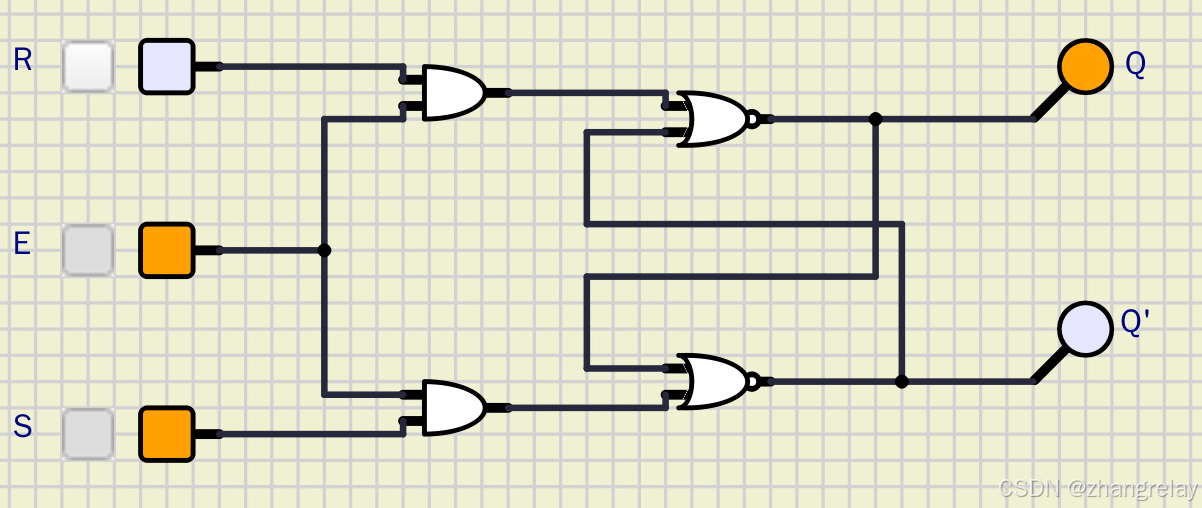 AI Visual Insight: This image highlights SimulIDE’s interactive simulation interface, especially component drag-and-drop, wiring, instrument coordination, and runtime observation. It is well suited for validating digital circuit behavior while adjusting parameters in real time.
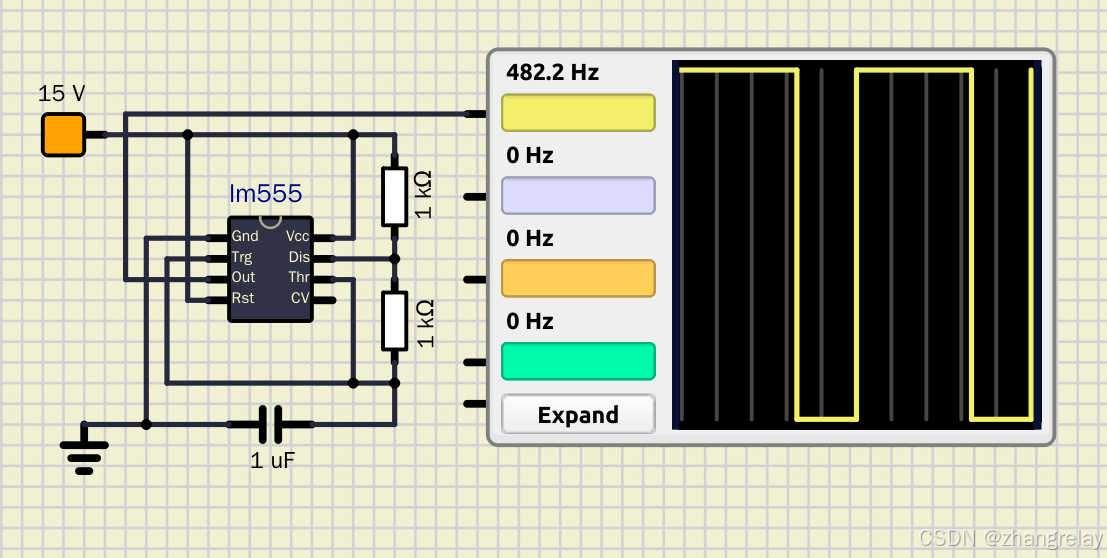 AI Visual Insight: This image corresponds to a 555 timer experiment scenario, commonly used to generate pulses, delays, or blinking waveforms. The key technical focus is the adjustable verification of duty cycle, oscillation frequency, and trigger mode.
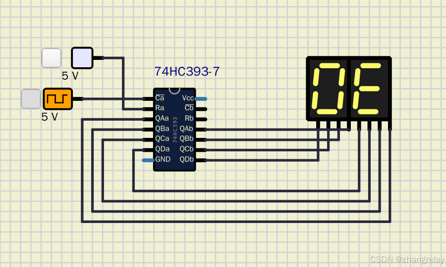
 AI Visual Insight: This image reflects a counter or timing circuit layout. Common building blocks include a clock source, flip-flop chains, and digital display modules, making it suitable for observing state transitions and counting cycles under clock-driven operation.
 AI Visual Insight: This image emphasizes a chip-level digital experiment setup, where 74LS-series logic devices, power rails, and probes are typically visible. It shows that SimulIDE is useful not only for conceptual demonstrations but also for chip-level validation.
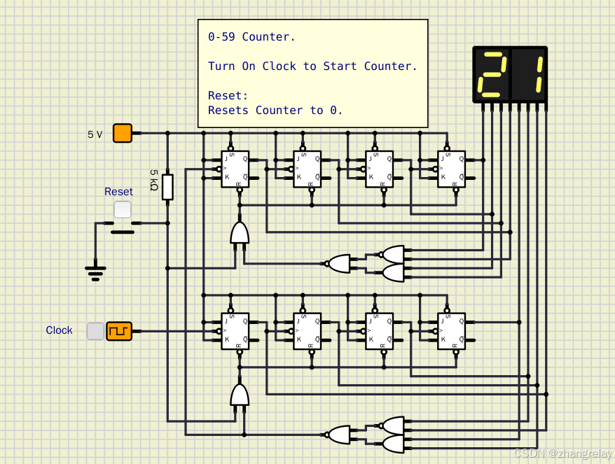 AI Visual Insight: This image continues the counter and timing theme and is especially useful for observing multi-bit output waveforms, frequency division relationships, and display decoding chains. It is a classic visual scenario for understanding the stateful nature of sequential logic.
SimulIDE Provides Low-Cost Digital System Validation Beyond Classroom Demonstrations
SimulIDE’s strength is not that it replaces professional EDA tools. Its real advantage is that it converts digital electronics concepts into observable behavior with an extremely low barrier to entry. For robotics, embedded systems, and introductory electronics courses, it directly shows how input changes affect output behavior and why those changes occur.
The most valuable part of the source material is its alignment between the official example directories and robot engineering scenarios. That is far more effective than discussing truth tables in isolation, because learners can directly map logic gates, flip-flops, and counters to emergency stops, safety doors, encoders, and fault displays.
These Six Official Example Categories Deserve Priority
examples/Digital/LogicGates/: Logic gates and 74LS chip verification.examples/Digital/Combinational/: Adders, decoders, and multiplexers.examples/Digital/FlipFlop/: RS, D, JK, and T flip-flops.examples/Digital/Counter/: Binary counting, up/down counting, and prescaling.examples/Analog/Digital/: 555 timer, PWM, Schmitt trigger, ADC/DAC.examples/Micro/Arduino/: Buttons, serial communication, servos, and I2C interaction.
# Organize official example paths by learning priority
example_groups = {
    "逻辑门": "examples/Digital/LogicGates/",
    "组合逻辑": "examples/Digital/Combinational/",
    "触发器": "examples/Digital/FlipFlop/",
    "计数器": "examples/Digital/Counter/",
    "数模混合": "examples/Analog/Digital/",
    "Arduino": "examples/Micro/Arduino/"
}

for name, path in example_groups.items():
    print(f"{name}: {path}")  # Print the core directory for each example category
This code quickly organizes the learning entry points for SimulIDE’s official examples.
Digital Electronics in Robotics First Appears as Hardware Safety and State Awareness
Logic gates form the first layer of a robot safety circuit. AND gates are suitable for “run only when all conditions are satisfied.” OR gates are ideal for “raise an alarm if any fault occurs.” NOT gates work well for state inversion and interlock indication.
Combinational logic is stateless, so any change at the input immediately changes the output. That makes it suitable for direction detection, data decoding, channel switching, and fault encoding. Sequential logic is different. It depends on a clock and preserves state, which makes it ideal for encoder counting, position accumulation, and fault latching.
Four Representative Robot Scenarios Cover the Main Digital Electronics Workflow
- Emergency-stop safety logic: AND, OR, NOT gates.
- Encoder direction detection: XOR gate, half adder.
- Pulse accumulation counting: JK flip-flop, asynchronous counter.
- Fault code display: BCD decoder, seven-segment display.
def safety_and_logic(inputs):
    return all(inputs)  # Allow operation only when all safety inputs are valid

def fault_or_logic(inputs):
    return any(i == 0 for i in inputs)  # Trigger an alarm if any input reports a fault

signals = [1, 1, 1, 1, 0]
print("运行使能:", safety_and_logic(signals))
print("故障报警:", fault_or_logic(signals))
This code abstracts the hardware logic essence of a robot safety interlock.
Encoder Decoding and Counters Are the Real Landing Zone for Digital Electronics in Robot Engineering
The source material repeatedly emphasizes encoder scenarios, and for good reason. One of the most fundamental questions in robotics is: how far did the mechanism move, which direction is it heading, and where is its current position? All of these depend on reliable digital signal processing.
XOR gates can help identify differences in quadrature signals. Half adders can combine pulse information. Cascaded JK flip-flops form counters that accumulate pulses. For students, this creates engineering intuition much more effectively than abstract derivations alone.
A Minimal Counter Model Is Enough to Show the Memory Property of Sequential Logic
count = 0
clock_edges = [1, 0, 1, 1, 0, 1]

for edge in clock_edges:
    if edge == 1:
        count += 1  # Increment the count on each valid rising edge

print("累计脉冲数:", count)
This minimal model shows that “clock-driven state accumulation” is the core behavior of a counter.
Decoders and Display Chains Can Support Everything from Teaching Panels to Fault Indicators
The value of a decoder is that it translates a machine’s internal binary state into output that humans can read. The most common case is BCD-to-seven-segment display conversion, which is used to show operating states, error codes, and local parameters.
In industrial settings, this kind of hardware display chain is stable, intuitive, and independent of a host computer. In teaching, the decoder is also a classic example of combinational logic, where the input uniquely determines the output.
The Recommended Learning Sequence Starts with Behavior, Then Theory, Then Transfer
Open six example types first: Logic_Gates, Adder, JK_FlipFlop, Counter_4bit, 555_Timer, and Button_LED. Focus on the input/output relationships. Then return to truth tables, characteristic tables, and timing waveforms. Finally, transfer that understanding to robot safety systems, encoders, and display subsystems.
This sequence works because the knowledge chain remains continuous: logic gates handle decision-making, combinational logic handles transformation, sequential logic handles memory, mixed-signal circuits handle shaping and pulse generation, and Arduino connects hardware logic to the software control stack.
FAQ
FAQ 1: Can SimulIDE replace Proteus or professional EDA tools?
Not completely. SimulIDE is better suited for teaching, rapid validation, and the transition from concept to prototype, especially for digital circuits, Arduino, and foundational robotics experiments.
FAQ 2: What should robotics students prioritize first when learning digital electronics?
Prioritize logic gates, flip-flops, counters, decoders, Schmitt triggers, and 555 timers. These map directly to safety interlocks, encoder counting, fault display, signal conditioning, and pulse generation.
FAQ 3: Why do many people memorize truth tables but still fail to build projects?
Because they lack scenario mapping. When you treat an AND gate as a safety interlock, a counter as a position ruler, and a decoder as a fault display, knowledge stops being a memorization exercise and becomes a design capability.
Core Summary: This article reconstructs the original SimulIDE digital electronics material into a dense technical guide for robot engineering. It organizes the official example directories, connects the knowledge chain from logic gates to sequential circuits, and uses four cases—emergency-stop interlocks, encoder decoding, counters, and fault display—to show how digital electronics translates into practical robot control.