Bluetooth HID relies on L2CAP to build a stable transport bridge between the application layer and the baseband ACL link. Its core capabilities include protocol adaptation, dual-channel traffic separation, and QoS assurance, solving the low-latency, compatibility, and reliability challenges of wireless input devices. Keywords: Bluetooth HID, L2CAP, QoS.
The technical specification snapshot provides a quick reference
| Parameter | Description |
|---|---|
| Protocol Topic | Bluetooth HID over L2CAP |
| Layer Position | Between host/device upper-layer protocols and the baseband ACL link |
| Typical Languages | C / C++ / embedded protocol stack implementations |
| Transport Mode | Connection-oriented L2CAP channels |
| Core Channels | Control Channel, Interrupt Channel |
| Key Parameters | PSM, CID, MTU, QoS, Flush Timeout |
| Minimum MTU | 48 bytes |
| Typical Dependencies | Bluetooth Core Specification, HID Profile, ACL Link |
| Article Source Characteristics | Original CSDN technical analysis, approximately 277 reads |
The L2CAP layer serves as the protocol bridge for Bluetooth HID wireless interaction
In the Bluetooth HID architecture, L2CAP is not a simple forwarding layer. It acts as both a protocol adapter and a logical channel manager. Upstream, it accepts HID messages. Downstream, it multiplexes the ACL link so that keyboards, mice, and game controllers can deliver an interaction experience close to wired USB HID.
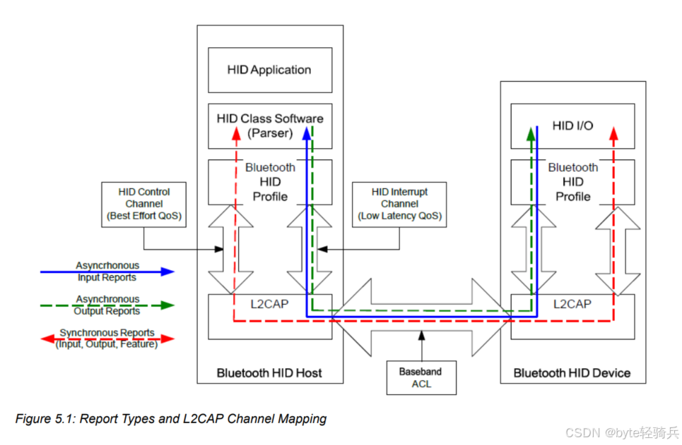 AI Visual Insight: This diagram shows L2CAP as the middle layer between the HID protocol and the underlying Bluetooth transport stack. It highlights L2CAP’s role in logical channel setup, data adaptation, and transmission scheduling, making it the critical bridge between HID application semantics and ACL link encapsulation.
L2CAP handles three core responsibilities: protocol adaptation, channel multiplexing, and quality-of-service assurance. The first two answer the question of how data is sent. The third answers whether data can arrive on time and reliably. That is the fundamental reason Bluetooth HID can balance low latency with cross-vendor interoperability.
The responsibilities of L2CAP can be abstracted as unified encapsulation and unified scheduling
typedef struct {
    uint16_t mtu;          // Maximum payload the channel can receive
    uint16_t cid;          // Logical channel identifier
    uint16_t psm;          // Protocol/service multiplexer identifier
    uint8_t service_type;  // Service type: Best Effort or Guaranteed
} hid_l2cap_channel_t;
This structure summarizes the most important L2CAP channel metadata in a HID implementation.
Bluetooth HID separates control traffic from real-time data through a dual-channel design
Bluetooth HID uses a dual-channel model with fixed responsibilities. The control channel carries non-real-time control messages, while the interrupt channel carries real-time input and output. This design prevents configuration traffic from blocking high-frequency input traffic.
The control channel typically carries device configuration, mode switching, Feature Reports, and similar messages. It prioritizes integrity and controllability, so its service type is usually Best Effort. The interrupt channel carries high-frequency data such as keyboard keystrokes, mouse movement, and game controller state. Its service type is Guaranteed, with a strong focus on low latency.
The channel establishment order is a hard compatibility requirement
void hid_open_channels(void) {
    open_control_channel();      // Open the control channel first
    config_control_channel();    // Complete MTU, QoS, and related configuration
    open_interrupt_channel();    // Then open the interrupt channel
}
This flow reflects a key requirement in the specification: control first, data second; configure first, transmit second.
The shutdown order is the reverse. Close the interrupt channel first, then close the control channel. If the ACL link drops unexpectedly, both logical channels must be treated as invalid to prevent stale protocol stack state from affecting reconnection.
The data encapsulation mechanism determines how HID messages enter the Bluetooth link
Raw HID reports cannot go directly into the baseband layer. They must first be encapsulated as HIDP messages, then wrapped by L2CAP with length and CID fields, and finally mapped into ACL transport units. This layered design reduces protocol coupling.
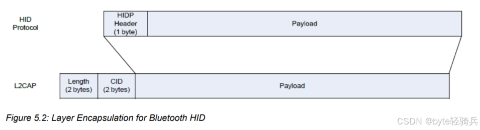 AI Visual Insight: This diagram illustrates the step-by-step encapsulation path from raw HID data to the HIDP header and then to the L2CAP header. It emphasizes how the 1-byte HIDP protocol header and the 4-byte L2CAP header together form a complete frame that can be transmitted over the ACL link.
void pack_hid_report(uint8_t *report, uint16_t len) {
    add_hidp_header(report, len);     // Add the HIDP header first to mark message semantics
    add_l2cap_header(report, len + 1);// Then add the L2CAP header to mark length and CID
    send_acl_packet(report);          // Finally send it over the ACL link
}
This code represents the minimum encapsulation flow that converts a HID message into a transmittable frame.
The sender must ensure that the message length does not exceed the negotiated MTU. If it does, the specification requires the packet to be dropped directly rather than relying on proprietary fragmentation. This rule is critical for device compatibility.
MTU and QoS parameters jointly define the upper bound of the interaction experience
MTU defines the maximum payload size that a single transmission can carry. In Boot Protocol Mode, the minimum requirement is typically 48 bytes. In Report Protocol Mode, the host-side receive capability must be larger, with common requirements at or above 672 bytes.
MTU negotiation usually completes during L2CAP channel setup, and the final value is the smaller of the two peers’ capabilities. Simple mice and keyboards usually do not need a large MTU, but game controllers with force feedback or complex report descriptors must reserve more receive space.
QoS parameters determine whether real-time input feels responsive
typedef struct {
    uint32_t token_rate;        // Number of bytes allowed per second
    uint32_t bucket_size;       // Burst traffic buffering capacity
    uint32_t latency_ms;        // Maximum acceptable latency
} hid_qos_t;
This structure reflects the three core variables most commonly tuned for the interrupt channel.
The interrupt channel often uses the Guaranteed service type and is tuned with parameters such as Token Rate, Latency, and Delay Variation. The control channel usually does not require strict QoS and only needs eventual delivery. If the system enables Sniff or Sniff Subrating, you must also evaluate the tradeoff between power consumption and latency.
Typical device configurations reveal the logic behind parameter selection
A mouse focuses on balancing low latency with low power consumption. A typical interrupt channel Token Rate can be 300 octets/sec, with Latency around 10 ms. That corresponds to roughly 100 reports per second, with each movement report carrying about 3 bytes.
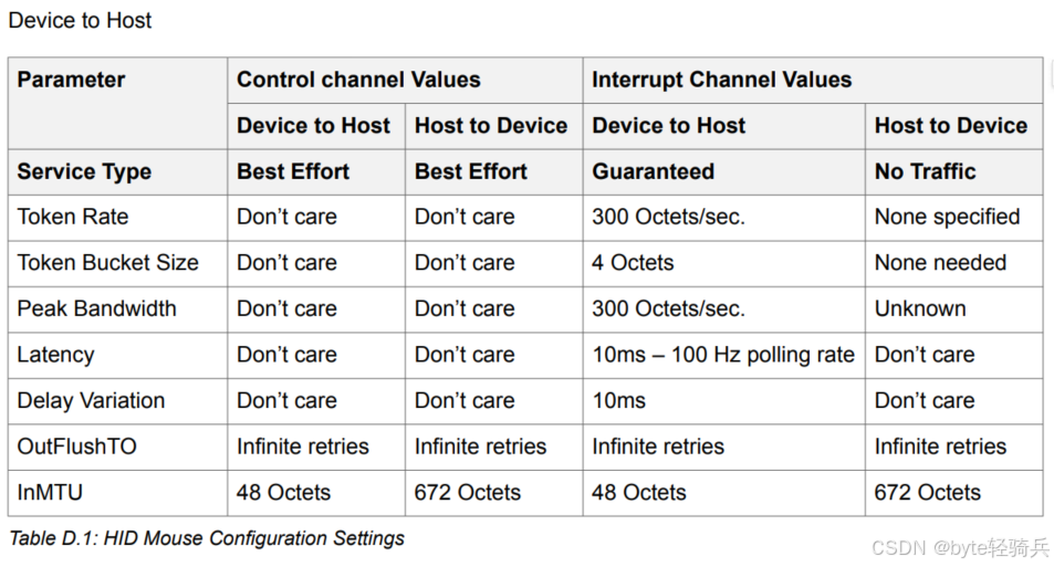 AI Visual Insight: This diagram focuses on an L2CAP parameter template for a mouse. It highlights the small-packet, high-frequency transmission pattern from device to host, which is well suited to a lower token rate and shorter latency to preserve pointer responsiveness while keeping power consumption low.
A keyboard has a bursty reporting pattern. In common devices, the device-to-host Token Rate can reach 900 octets/sec, and the host-to-device direction must also reserve bandwidth for LED state control.
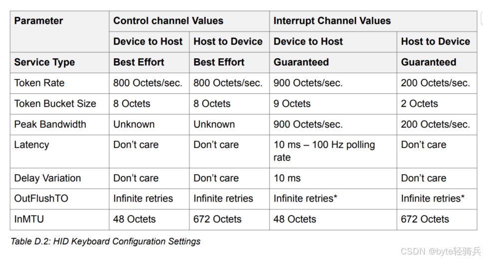 AI Visual Insight: This diagram shows the configuration priorities of a keyboard’s bidirectional interrupt channel. One direction guarantees frequent upload of key scan codes, while the other ensures delivery of LED state changes such as Caps Lock, reflecting the keyboard’s stronger bidirectional interaction requirements compared with a mouse.
Game controllers typically have the highest bidirectional bandwidth requirements. In the host-to-device direction, the host often also sends force-feedback commands, so the Token Rate may exceed the device-to-host direction.
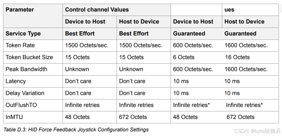 AI Visual Insight: This diagram shows the high-bandwidth configuration pattern of a force-feedback controller in the host-to-device direction. It demonstrates that, in addition to uploading button and joystick data, the device also requires stable delivery of vibration, damping, and similar effect commands, so its QoS budget is noticeably higher than that of traditional peripherals.
Sequence, length, and power-management strategy are the most common implementation pitfalls
In engineering practice, you should check three categories of issues first: whether the channel establishment order follows the specification, whether the maximum report length is smaller than the negotiated MTU, and whether Sniff-related low-power settings introduce extra latency.
If you see high input latency, occasional packet loss, or abnormal reconnection behavior, start troubleshooting with interrupt channel Latency, buffer size, Flush Timeout, and link supervision timeout. In HID scenarios, avoid proprietary flow-control schemes whenever possible and prefer standard L2CAP mechanisms.
A simplified troubleshooting checklist helps validate the stack quickly
bool hid_l2cap_self_check(void) {
    if (!control_opened_first) return false;   // Open the control channel first
    if (interrupt_mtu < 48) return false;      // Minimum MTU requirement
    if (flush_timeout != 0xFFFF) return false; // Avoid flushing critical data
    return true;
}
This validation logic works well as a fast self-check entry point after protocol initialization.
FAQ structured answers clarify the most common design questions
1. Why must Bluetooth HID separate the control channel from the interrupt channel?
Because the two traffic classes have different goals. Control traffic emphasizes reliable configuration, while interrupt traffic emphasizes low-latency real-time response. By separating them, the system can apply differentiated scheduling over the same ACL link and prevent control messages from blocking input events.
2. Why should you not set the MTU arbitrarily small in HID scenarios?
If the MTU is smaller than the maximum report length, packets will be dropped directly or trigger compatibility issues. This is especially important for complex game controllers and devices with Report IDs, where the receive MTU must cover the full HIDP payload.
3. Why does a device feel laggy after low-power mode is enabled?
A common cause is an overly long Sniff interval or a mismatch between QoS and low-power parameters. If the interrupt channel Latency budget is smaller than the wake-up delay from low-power mode, input lag becomes visible. You need to rebalance battery life and responsiveness.
Core Summary: This article systematically reconstructs the design of the L2CAP layer in the Bluetooth HID specification. It focuses on the control/interrupt dual-channel model, data encapsulation, MTU negotiation, QoS assurance, and typical device configurations to help developers understand how Bluetooth keyboards, mice, and game controllers achieve low-latency and highly compatible communication.