[AI Readability Summary] In-memory systems centralize core business state in memory, use Write-Ahead Logging (WAL) and snapshots for recoverability, and rely on event-driven execution to preserve ordering. This architecture fits high-concurrency workloads, real-time computation, and complex atomic business operations. Keywords: in-memory systems, WAL, snapshot recovery.
Technical specifications define the architecture at a glance
| Parameter | Description |
|---|---|
| Domain | Distributed Architecture / High-Concurrency System Design |
| Core Idea | Memory as the state store, log first, recover with snapshots |
| Primary Mechanisms | WAL, Snapshot, Event-Driven Execution, Single Writer |
| Typical Languages | Java, Go, C++ |
| Protocol / Communication Model | RPC, Event Streams, Ordered Message Processing |
| GitHub Stars | Not provided in the source |
| Core Dependencies | Persistent logs, snapshot storage, in-memory data structures |
Traditional database-driven architectures expose systemic bottlenecks under high concurrency
Traditional internet systems usually treat the database as the single source of truth, while the service layer only reads from and writes to tables. This model is fast to build and easy to understand. However, as request volume, concurrent writes, and business complexity increase, the database shifts from a storage layer into the central bottleneck for both performance and consistency.
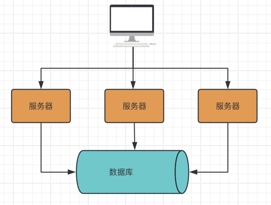
AI Visual Insight: The diagram shows a typical database-centric architecture. Application requests must frequently access the database to read and write state. Business state and computation are spread across multiple I/O operations, which often introduces lock contention, oversized transactions, and expensive consistency coordination.
The core problems in the traditional model center on I/O, locks, and transactions
First, database I/O latency is inherently higher than memory access latency. A single 1-2ms operation may look small, but repeated across a high-frequency call chain, it compounds quickly and eventually hurts both throughput and tail latency.
Second, when multiple requests concurrently modify the same state, the system must rely on locks, transactions, or compensation mechanisms to preserve consistency. This rapidly increases complexity and forces performance and correctness to constrain each other.
Request -> Query database -> Business computation -> Update multiple tables -> Commit transaction
                     # Every step can introduce I/O and lock contention
This flow makes the bottleneck clear: the problem in the traditional model is not one slow code path, but the combined cost of repeated remote access and transaction coordination.
In-memory systems rebuild the execution model by converging state into memory
The core of an in-memory system is not simply using a cache to accelerate reads. Instead, it moves the business source of truth from the database into memory, so state transitions happen inside a single execution context. The database is demoted from an online source of truth to a persistence and recovery medium.
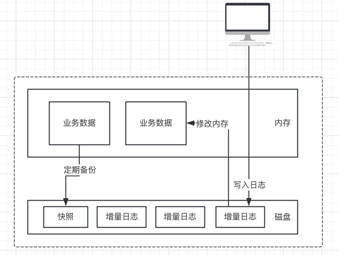
AI Visual Insight: The diagram shows the closed-loop state model in an in-memory architecture. Requests are first converted into events. After the events are durably written to the log, they drive in-memory state transitions. Snapshots and logs then support disaster recovery. This structure emphasizes ordered execution, centralized state, and replayable recovery.
The four foundational components of an in-memory system are all essential
- Memory as the state store: Core business state such as balances, inventory, queues, and counters lives directly in memory.
- WAL first: Record the operation in the log before modifying memory, so the system can replay it after a crash.
- Periodic snapshots: Persist the current in-memory state to disk to shorten restart and recovery time.
- Event-driven execution: Convert external requests into events and process them in order to advance state.
class MemoryEngine:
    def handle_event(self, event):
        self.append_wal(event)      # Write WAL first to guarantee recoverability
        self.apply(event)           # Then update in-memory state
        if self.need_snapshot():    # Generate a snapshot when conditions are met
            self.save_snapshot()
This code captures the minimum execution loop of an in-memory system: log first, apply to memory, and use snapshots as the safety net.
In-memory systems emphasize ordering, atomicity, and recoverability more than traditional architectures
In a database-driven model, consistency usually depends on underlying transactions. In an in-memory model, consistency comes more from ordered execution and the single-writer principle. As long as one state boundary has only one write entry point, conflicts drop significantly.
The differences between the two architectures appear in the source of truth and concurrency control model
| Dimension | Traditional Internet System | In-Memory System |
|---|---|---|
| Source of Truth | Database | Memory + WAL |
| Concurrency Control | Locks / Transactions | Single Writer / Partitioned Ordering |
| Ordering Guarantee | Weak ordering or eventual consistency | Strong ordering, replayable |
| Performance Profile | I/O-bound, millisecond-level | Memory access, microsecond-level |
| Disaster Recovery | Rollback, compensation | Snapshot + log replay |
public void process(Command cmd) {
    wal.write(cmd);           // Write the log first; the log is the success boundary
    stateMachine.apply(cmd);  // Apply the change to in-memory state in order
}
This code reflects the most important design principle of an in-memory system: success is defined not by a database commit, but by WAL persistence.
In-memory systems fit high-frequency writes and complex atomic business workflows
When a business requires high concurrency, low latency, and multiple state changes that must complete as one atomic step, the in-memory approach provides clear advantages. Matching engines, real-time risk control, inventory deduction, gateway counters, and online metric aggregation are all typical examples.
The benefits of this architecture come from centralized state, not cache hit rates
Centralized state means one business operation can complete within the same in-memory context. The system no longer needs cross-table access, repeated queries, or large transaction coordination. The result is not only higher speed, but also better guarantees for atomicity and execution order in complex workflows.
Event A -> WAL persisted -> In-memory state updated -> Result published externally
Event B -> WAL persisted -> In-memory state updated -> New snapshot generated
This flow shows that an in-memory system behaves more like a replayable state machine than a database application with a cache.
In-memory systems are not a silver bullet but a high-bar architecture choice
Their greatest value lies in performance and determinism, but the trade-offs are equally significant. Once memory becomes the source of truth, any log corruption, snapshot failure, OOM event, or bad release can directly threaten system availability.
Second, scalability is not automatically elegant. A single state boundary usually allows only one writer. Horizontal scaling must be built on explicit partitioning, or the system will lose ordering guarantees.
Recovery paths and state boundaries must come first in the design
Without a reliable WAL, snapshot strategy, version compatibility plan, and replay tooling, an in-memory system becomes harder to debug than a CRUD application. It requires teams to think in terms of state machines, run failure drills, and enforce strict engineering discipline.
def recover(snapshot, wal_records):
    state = load_snapshot(snapshot)   # Load the latest snapshot first
    for record in wal_records:
        apply(state, record)          # Replay incremental logs in order
    return state
This code shows that recoverability is a prerequisite for an in-memory system, not an optional feature.
The conclusion is that an in-memory system is fundamentally a business state machine architecture
It does not simply put data into memory. It unifies business state, execution order, and recovery into a single replayable model. Databases are better suited for archival and offline persistence, while in-memory systems are better suited for real-time decision-making and high-frequency state progression.
If your system is consistently constrained by database I/O, transaction bloat, and complex consistency issues, and if your business boundaries are clear and your state model is stable, then an in-memory design deserves serious consideration.
FAQ
1. What is the fundamental difference between an in-memory system and a Redis cache architecture?
A Redis cache is usually just an acceleration layer in front of the database, while the database remains the source of truth. In an in-memory system, the in-memory state itself becomes the source of truth, and WAL plus snapshots guarantee recovery.
2. Why can in-memory systems enforce atomicity more easily?
Because multiple pieces of business state can be updated sequentially inside the same in-memory context, the system does not need cross-table transaction coordination. Atomicity depends mainly on single-threaded ordered execution or a single-writer model rather than heavyweight database transactions.
3. When should you avoid adopting an in-memory system?
If write frequency is low, state boundaries are unclear, or the team lacks engineering experience in log recovery and state-machine design, you should avoid adopting it too quickly. The design, operations, and recovery bar is clearly higher than in a standard CRUD architecture.
Core Summary: This article systematically explains in-memory system design: why traditional database-driven models hit performance, consistency, and atomicity bottlenecks under high concurrency, and how memory-resident state, WAL, snapshots, and event-driven execution can build a high-performance, strongly ordered, and recoverable business engine.